Controllable micro light assembly

a micro-light and assembly technology, applied in the field of metal systems, can solve the problems of limiting the throughput of a vision system, prolonging the required exposure time, slow adjustment response time of light sources using mechanical adjustments, etc., and achieves small mechanical motion, large angular adjustment, and high speed

Active Publication Date: 2011-12-27
MITUTOYO CORP
View PDF20 Cites 30 Cited by
  • Summary
  • Abstract
  • Description
  • Claims
  • Application Information

AI Technical Summary

Benefits of technology

In accordance with another aspect of the invention, in various embodiments, the connection element that receives and holds the micro light interface assembly according to this invention may comprise an autojoint connection used with a touch probe head. The micro light interface assembly may be interchangeably mounted to and powered by a touch probe head that is used in conjunction with a microscopic machine vision inspection system. That is, when a touch probe is not in use, interchangeable micro light interface assemblies may be picked up and micro light assembly manipulated into desired positions relative to an objective lens and / or FOV on a workpiece surface using the touch probe head and its associated motion system. Thus, a micro light interface assembly according to this invention allows significant new abilities and utility to be derived from standard touch probe control techniques already used in conjunction with some machine vision inspection system applications. In some embodiments, known touch probe control techniques may provide for up to 6 degrees of freedom of the motion usable to manipulate a micro ring light according to this invention, relative to a microscope objective lens and / or FOV. This allows a micro light assembly according to this invention to be precisely and flexibly positioned very close to the FOV on a workpiece that is being inspected, and / or a micro light interface assembly to be automatically exchanged with another that is more suited for a particular lens or a particular workpiece feature in the FOV, for example. The touch probe head may change the position and / or angle of the micro light assembly at a very high speed, due to its small mass.
In some embodiments, the micro light interface assembly may include a miniature or micro mechanical adjustment element that may assist in adjusting angle of incidence and / or azimuthal angle provided by the micro light assembly. Due to the miniature dimensions of the micro light assembly and its close proximity to the FOV, relatively large angular adjustments may be provided by relatively small mechanical motions. Thus, the adjustment response time of such mechanical adjustment elements may be much faster than that obtainable in known controllable light sources using mechanical adjustment elements.

Problems solved by technology

For example, lights sources which use mechanical adjustments typically have a slow adjustment response time that may limit the throughput of a vision system configured to acquire dozens of images without stopping the motion of the vision system at each feature, but rather by freezing each image using strobe illumination.
Such devices typically extend in various directions beyond the objective lens of the vision system, interfering with the positioning of some workpieces.
Thus, the 1 / r^2 drop in illumination intensity from the source limits the illumination intensity at the field of view, which extends the required exposure time for an image, limiting the throughput of a vision system that uses strobe illumination, for example.

Method used


Image

  • Controllable micro light assembly
  • Controllable micro light assembly
  • Controllable micro light assembly

Examples


Embodiment Construction

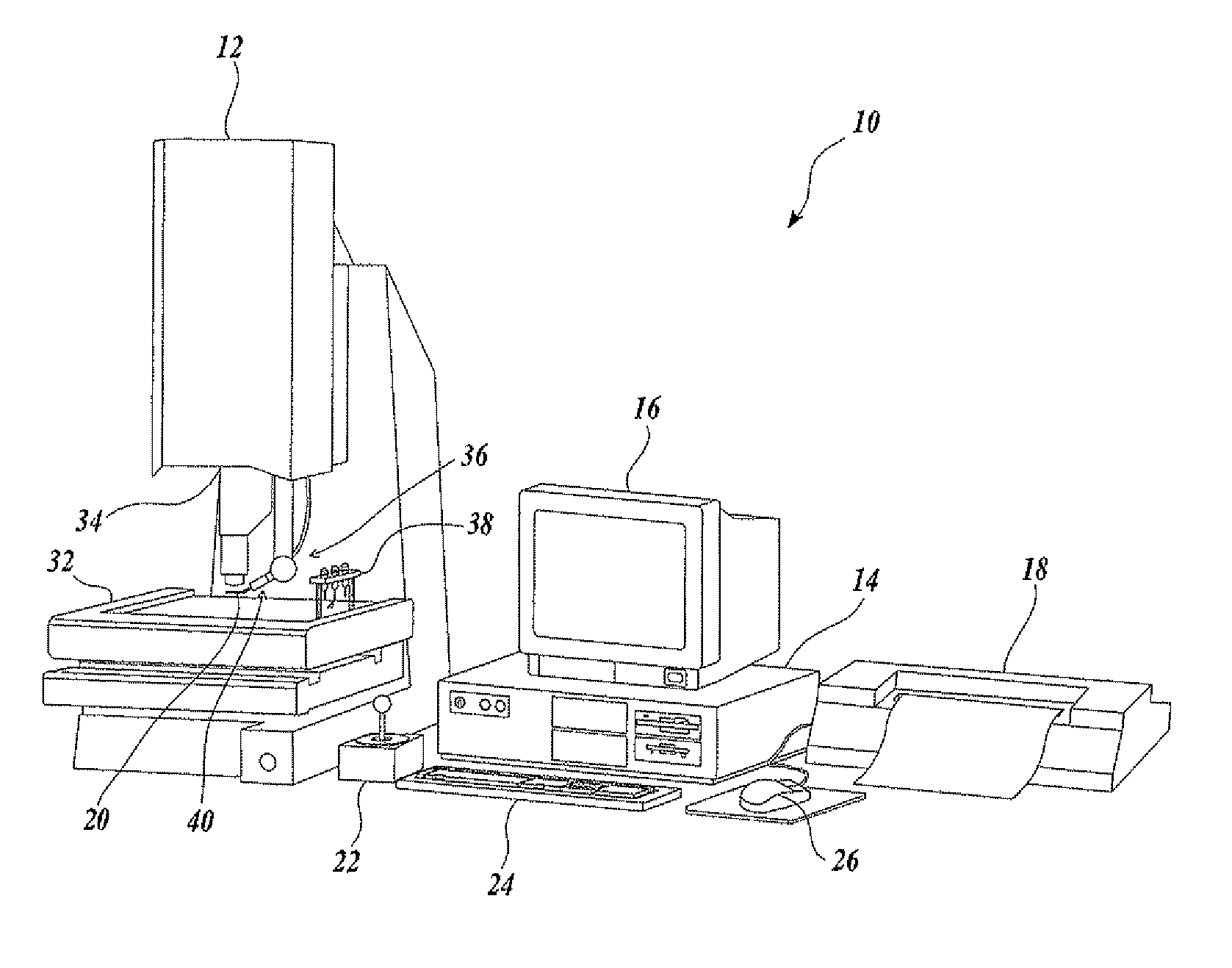
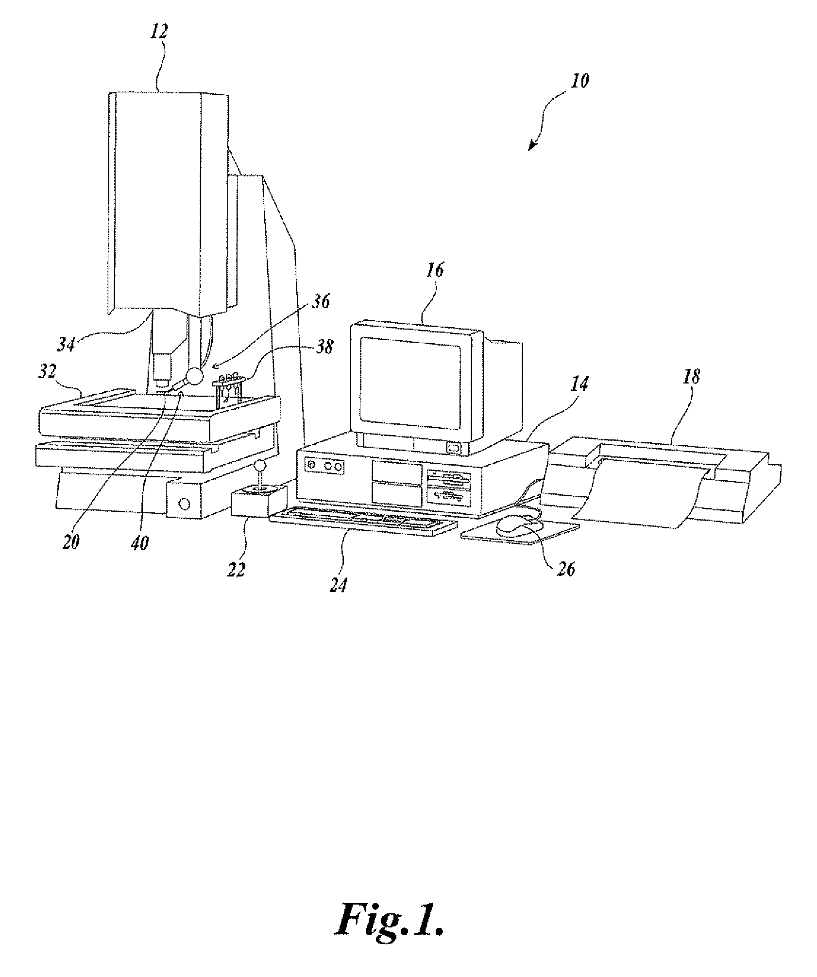
FIG. 1 is a block diagram of an exemplary microscopic-type machine vision inspection system 10 including one embodiment a micro light assembly according to this invention. The machine vision inspection system 10 includes a vision measuring machine 12 that is operably connected to exchange data and control signals with a controlling computer system 14. The controlling computer system 14 is further operably connected to exchange data and control signals with a monitor or display 16, a printer 18, a joystick 22, a keyboard 24, and a mouse 26. The monitor or display 16 may display a user interface suitable for controlling and / or programming the operations of the machine vision inspection system 10.

The vision measuring machine 12 includes a moveable workpiece stage 32 and an optical imaging system 34 which may include a zoom lens or interchangeable lenses. The zoom lens or interchangeable lenses generally provide various magnifications for the images provided by the optical imaging syste...


PUM


Abstract

A micro light interface assembly for a microscopic machine vision inspection system includes a micro light assembly. The micro light assembly provides addressable light emitting elements arranged around the periphery of an aperture having an aperture dimension DAPMIN that is smaller than a barrel dimension DBAR of the inspection system objective lens. The aperture may be located along the optical axis and within the working distance of the objective lens such that the light emitting elements are closely arranged around a field of view. The micro light interface assembly may be held and operated through a connection element that may be used for the interchanging the micro light interface assembly with a touch probe, in some embodiments.

Description

FIELD OF THE INVENTIONThe invention relates generally to metrology systems, and more particularly to a micro light assembly that may be utilized as part of a machine vision inspection system.BACKGROUNDPrecision machine vision inspection systems (or “vision systems” for short) can be utilized to obtain precise dimensional measurements of inspected objects and to inspect various other object characteristics. Such systems may include a computer, a camera and optical system, and a precision stage that is movable in multiple directions so as to allow the camera to scan the features of a workpiece that is being inspected. One exemplary prior art system that is commercially available is the QUICK VISION® series of PC-based vision systems and QVPAK® software available from Mitutoyo America Corporation (MAC), located in Aurora, Ill. The features and operation of the QUICK VISION® series of vision systems and the QVPAK® software are generally described, for example, in the QVPAK 3D CNC Vision...

Claims


Application Information

Patent Timeline
Patent Type & Authority Patents(United States)
IPC IPC(8): H04N7/18G06K9/42
CPCG02B21/06H04N5/2256G02B21/365H04N23/56
Inventor TOBIASON, JOSEPH D.GLADNICK, PAUL G.
Owner MITUTOYO CORP
Why Eureka
Try Eureka