Method and system for performing improved timing window analysis

a timing window analysis and timing window technology, applied in the field of improved approach for designing, analyzing, and manufacturing integrated circuits, can solve the problems of significant yield loss, complex process of performing crosstalk analysis, and more difficult problems

Inactive Publication Date: 2011-12-27
CADENCE DESIGN SYST INC
View PDF16 Cites 5 Cited by
  • Summary
  • Abstract
  • Description
  • Claims
  • Application Information

AI Technical Summary

Benefits of technology

[0005]Rapid developments in the technology and equipment used to manufacture semiconductor ICs have allowed electronics manufacturers to create smaller and more densely packed chips in which the IC components, such as wires, are located very close together. When electrical components are spaced close together, the electrical characteristics or operation of one component may affect the electrical characteristics or operation of its neighboring components. The reaction or noise that is triggered by this interference between components is called the “crosstalk” effect.

Problems solved by technology

These variations are commonly caused by side-effects of the processing used to manufacture the IC.
The process of performing crosstalk analysis is very complex, and is made even more difficult because of the effects of process variations.
This is because crosstalk can cause functional or timing failures of the chip, thus leading to significant loss of yield.
Because of the complexity for performing crosstalk analysis, analysis tools generally tend to err on the side of pessimism, on the theory that it is better for the tool to overestimate a noise, rather than take the risk of underestimating a potential point of failure.
Only those aggressor nets that have switching activities in the same window can potentially attack a victim at the same time.
However, timing windows themselves are approximate constructs, since they do not have any equivalent analytical description as a bound-based definition.
When used incorrectly, the timing windows can itself lead to excessive pessimism, or worse, optimism.

Method used


Image

  • Method and system for performing improved timing window analysis
  • Method and system for performing improved timing window analysis
  • Method and system for performing improved timing window analysis

Examples


Embodiment Construction

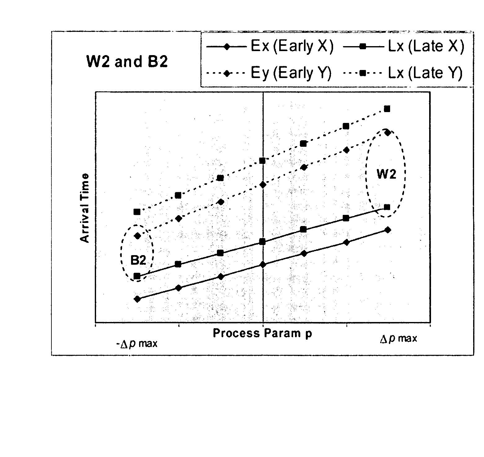
[0021]The present invention provides a method, system, and computer program product for performing analysis using timing windows. As noted above, one of the key methods used for noise analysis is the use of timing windows. According to some embodiments of the invention, first-order parameterized analysis modeling is used to overcome the shortcomings of the existing approaches, and factor in the effect of process variations within the definition of timing windows.

[0022]To explain the benefit of the present invention, it is helpful to discuss the limitations of other approaches to using timing windows. It is noted that timing windows are approximate constructs, and they therefore do not have any equivalent analytical description as a bound-based definition. When used incorrectly, the timing windows can itself lead to excessive pessimism, or worse, optimism.

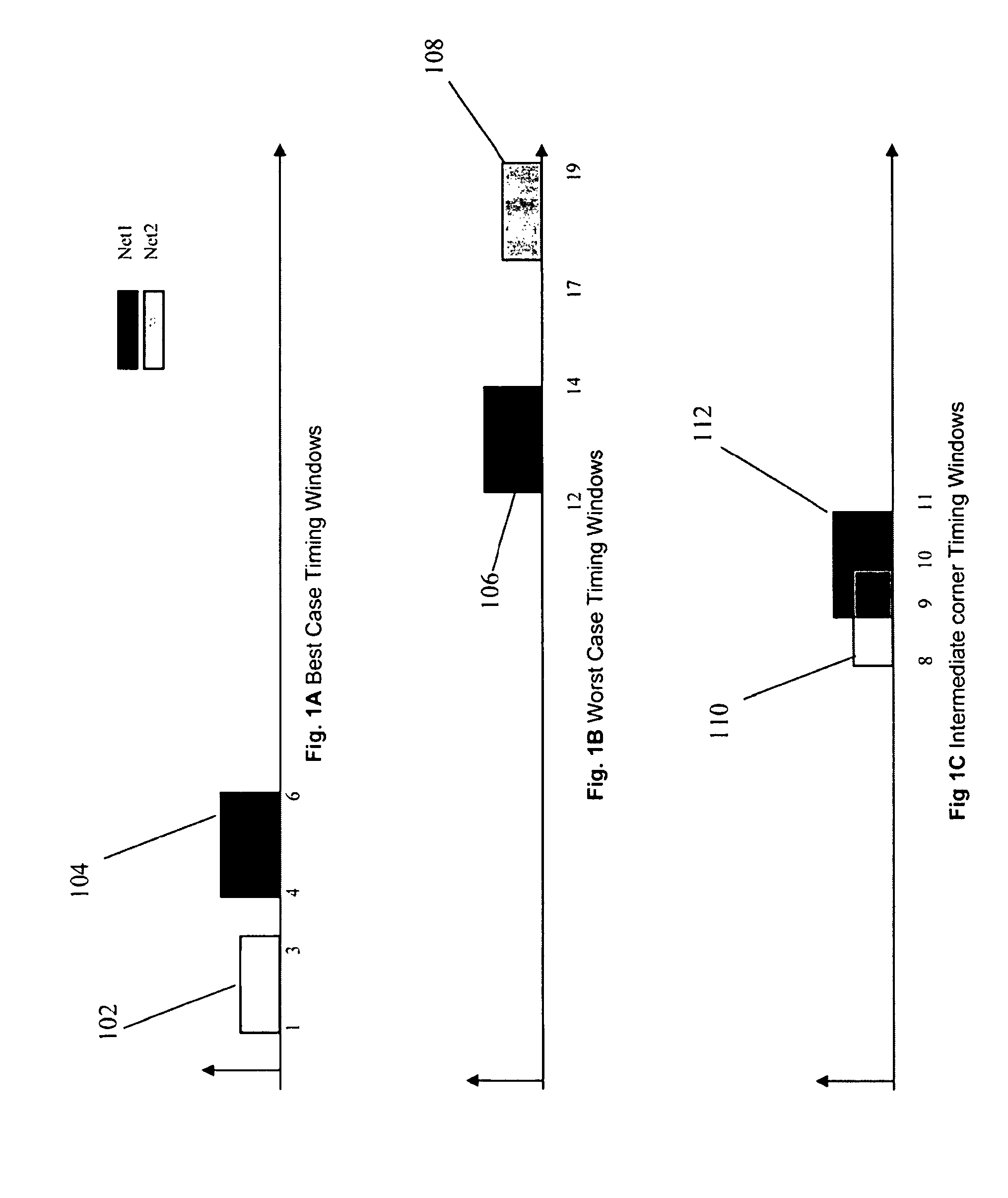
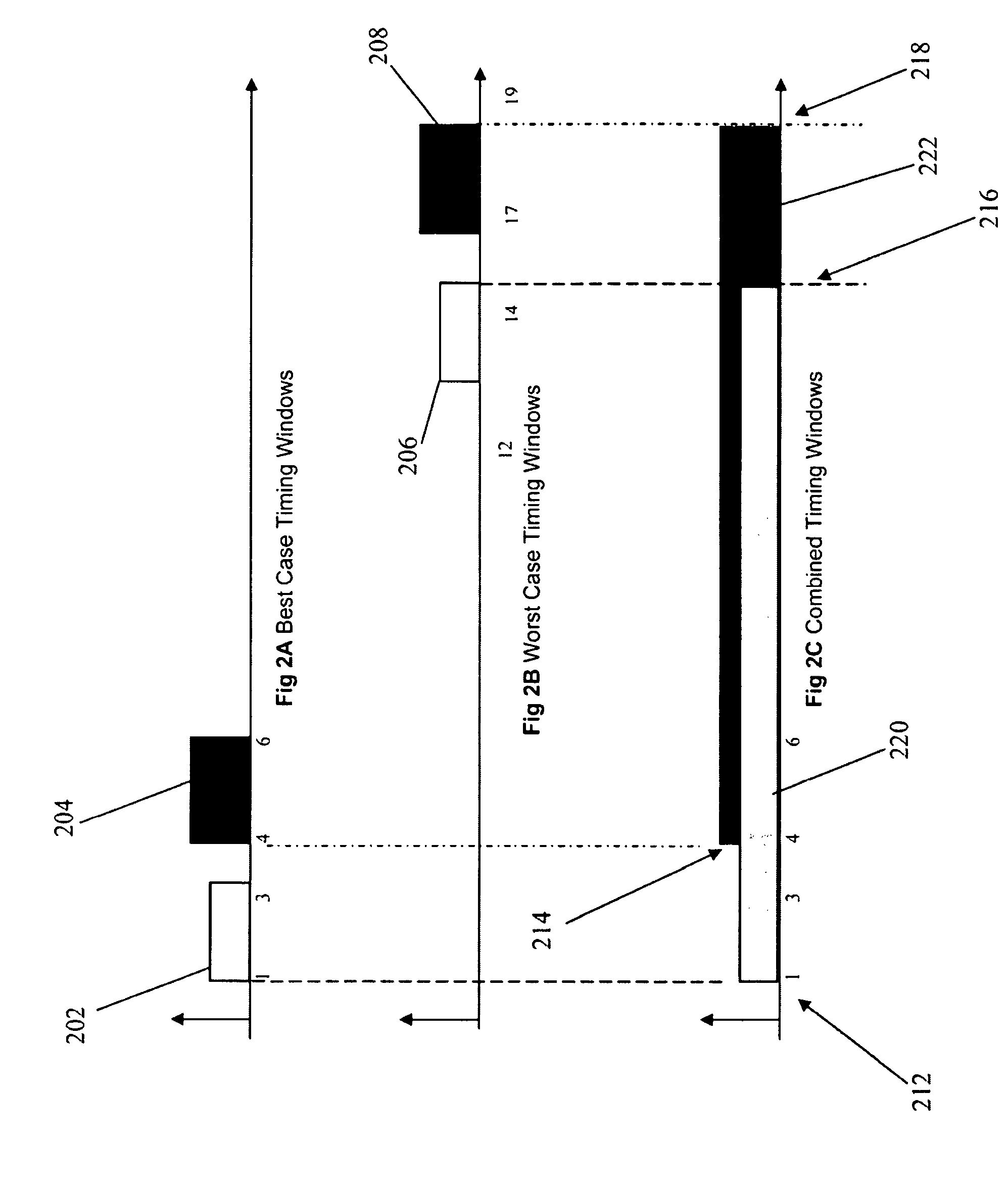
[0023]A primary example of this is the use in best-case / worst-case analysis, where timing windows corresponding to the best-case c...


PUM


Abstract

A method, system, and computer program product are disclosed for performing crosstalk analysis using first-order parameterized analysis modeling. The approach can be used to factor in the effect of process variations within the definition of timing windows. This approach allows one to bypass the simplistic assumptions related to best-case / worst-case analysis using timing windows, and provide a realistic picture of the impact of timing windows on noise analysis. The timing windows can be viewed in terms of the individual process parameter. The process parameters could be real process parameters, or virtual / computed components based on the actual process parameters. The process parameters can be used to compute overlap of timing windows for performing noise analysis.

Description

BACKGROUND AND SUMMARY[0001]The invention is directed to an improved approach for designing, analyzing, and manufacturing integrated circuits.[0002]An integrated circuit (IC) has a large number of electronic components, such as transistors, logic gates, diodes, wires, etc., that are fabricated by forming layers of different materials and of different geometric shapes on various regions of a-silicon wafer. Many phases of physical design may be performed with computer aided design (CAD) tools or electronic design automation (EDA) systems. To design an integrated circuit, a designer first creates high level behavior descriptions of the IC device using a high-level hardware design language. An EDA system typically receives the high level behavior descriptions of the IC device and translates this high-level design language into netlists of various levels of abstraction using a computer synthesis process. A netlist describes interconnections of nodes and components on the chip and include...

Claims


Application Information

Patent Timeline
Patent Type & Authority Patents(United States)
IPC IPC(8): G06F17/50
CPCG06F17/5036G06F2217/82G06F2119/10G06F30/367
Inventor SHRIVASTAVA, SACHINPARAMESWARAN, HARINDRANATH
Owner CADENCE DESIGN SYST INC
Why Eureka
Try Eureka