Display device
a display device and display technology, applied in the field of display devices, can solve the problems of increasing the number of output pins of the driver lsi, reducing the circuit area, and increasing the size of the frame area, so as to reduce the current consumption, and affect the effect of
- Summary
- Abstract
- Description
- Claims
- Application Information
AI Technical Summary
Benefits of technology
Problems solved by technology
Method used
Image
Examples
first embodiment
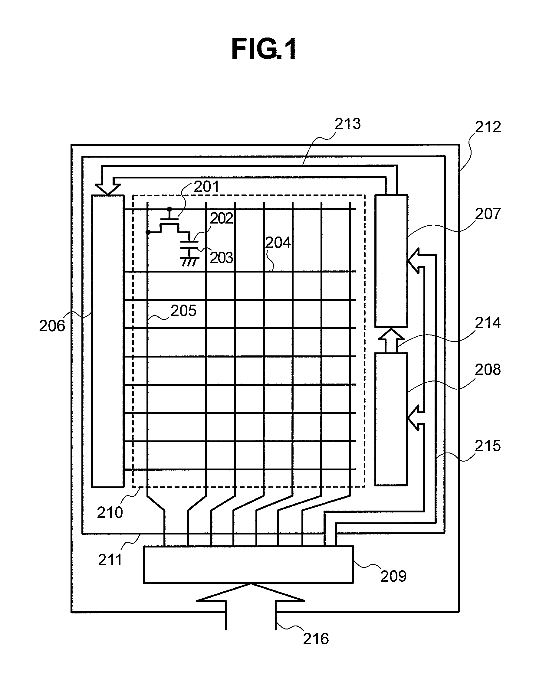
[0031]FIG. 1 is a block diagram showing a display device according to a first embodiment of the present invention. In FIG. 1, the display device according to this embodiment includes a liquid crystal panel 211 and a driver LSI 209 for driving the liquid crystal panel both provided on an insulating substrate 212. Disposed on the liquid crystal panel 211 in the horizontal direction and vertical direction are many gate lines 204 and many drain lines 205, respectively. Disposed at an intersection of each gate line 204 and each drain line 205 is a pixel, which includes a pixel electrode 202, a counter electrode 203, and a switching element 201. These components constitute a display area 210. Disposed on the periphery of the display area 210, that is, on the frame area are a power supply circuit 208, a level shifter circuit block 207, and a gate drive circuit 206.
[0032]The driver LSI 209 generates a control clock 215 to be provided to the power supply circuit 208 and level shifter circuit...
second embodiment
[0050]An inverter circuit according to a second embodiment of the present invention includes two output buffers. Thus, the inverter circuit is less affected by the CR time constant based on the resistance load R and a transistor parasite capacitance C included in the inverter circuit. Also, even if the resistance load R is increased, an output waveform of the inverter circuit rises and falls quickly. This embodiment will be described below with reference to FIGS. 5 and 6. The configuration of this embodiment except for that of the inverter circuit is the same as that of the first embodiment and will not be described.
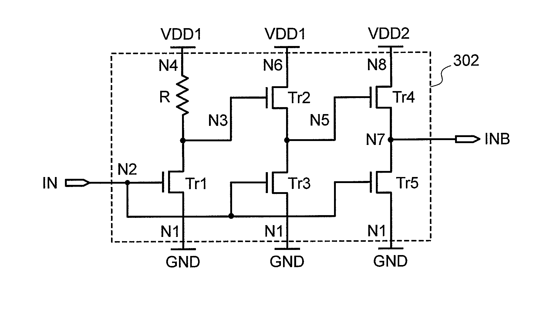
[0051]FIG. 5 is a diagram showing a configuration of the inverter circuit according to this embodiment. In FIG. 5, the inverter circuit 302 includes an input inverter having the high-resistance load R and transistor Tr1, an intermediate buffer having the transistors Tr2 and Tr3, and an output buffer having transistors Tr4 and Tr5. The sources of the transistors Tr1, tR3,...
third embodiment
[0061]In an third embodiment of the present invention, the power supply voltage VDD of the level shifter circuit block 207 is used instead of the power supply voltage VDD1 that is a higher one of the power supply voltages used by the inverter circuit. This reduces the number of power supply voltages required to operate the integrated circuit, thereby reducing the number of control clocks of the integrated circuit.
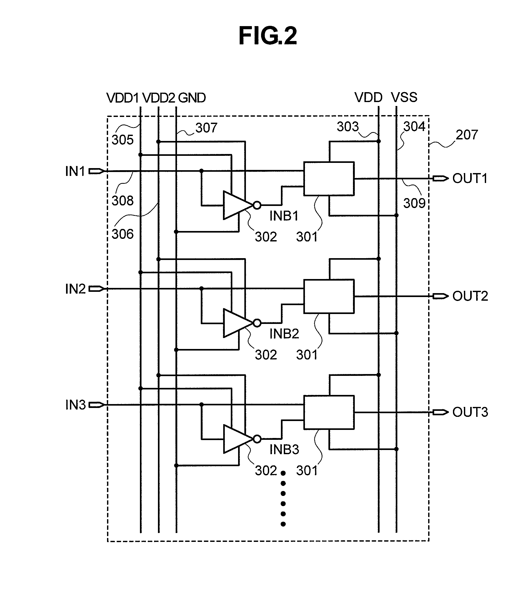
[0062]FIG. 7 is a diagram showing a configuration of the level shifter circuit block 207 according to this embodiment. In FIG. 7, the level shifter circuit block 207 includes the level shifter circuit 301 for increasing the amplitude of a control clock outputted from the driver LSI 209 shown in FIG. 1 and the inverter circuit 302 for generating an inverted clock INB required to operate the level shifter circuit 301. The inverter circuit 302 is the same as that used in the first or second embodiment, so the configuration and operation thereof will not be described.
[0063]Acco...
PUM
 Abstract
Description
Claims
Application Information
 - R&D
- Intellectual Property
- Life Sciences
- Materials
- Tech Scout
- Unparalleled Data Quality
- Higher Quality Content
- 60% Fewer Hallucinations
Browse by: Latest US Patents, China's latest patents, Technical Efficacy Thesaurus, Application Domain, Technology Topic, Popular Technical Reports.
© 2025 PatSnap. All rights reserved.Legal|Privacy policy|Modern Slavery Act Transparency Statement|Sitemap|About US| Contact US: help@patsnap.com


