Fuel control system with metering purge valve for dual fuel turbine

a technology of purge valve and fuel control system, which is applied in the direction of turbine/propulsion fuel valve, machine/engine, transportation and packaging, etc., can solve the problem achieve the effect of reducing the susceptibility of coking

Active Publication Date: 2012-01-31
JANSENS AIRCRAFT SYST CONTROLS
View PDF9 Cites 37 Cited by
  • Summary
  • Abstract
  • Description
  • Claims
  • Application Information

AI Technical Summary

Benefits of technology

[0015]The present invention addresses the shortcomings of the prior art by incorporating a unique metering purge valve in the fuel control system of a turbine system, and especially a dual fuel turbine. In a single valve package, the metering purge valve provides metering contro

Problems solved by technology

Furthermore, actively cooling the metering pur

Method used


Image

  • Fuel control system with metering purge valve for dual fuel turbine
  • Fuel control system with metering purge valve for dual fuel turbine
  • Fuel control system with metering purge valve for dual fuel turbine

Examples


Embodiment Construction

)

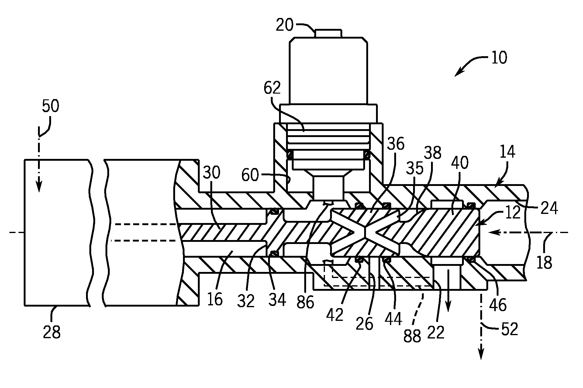
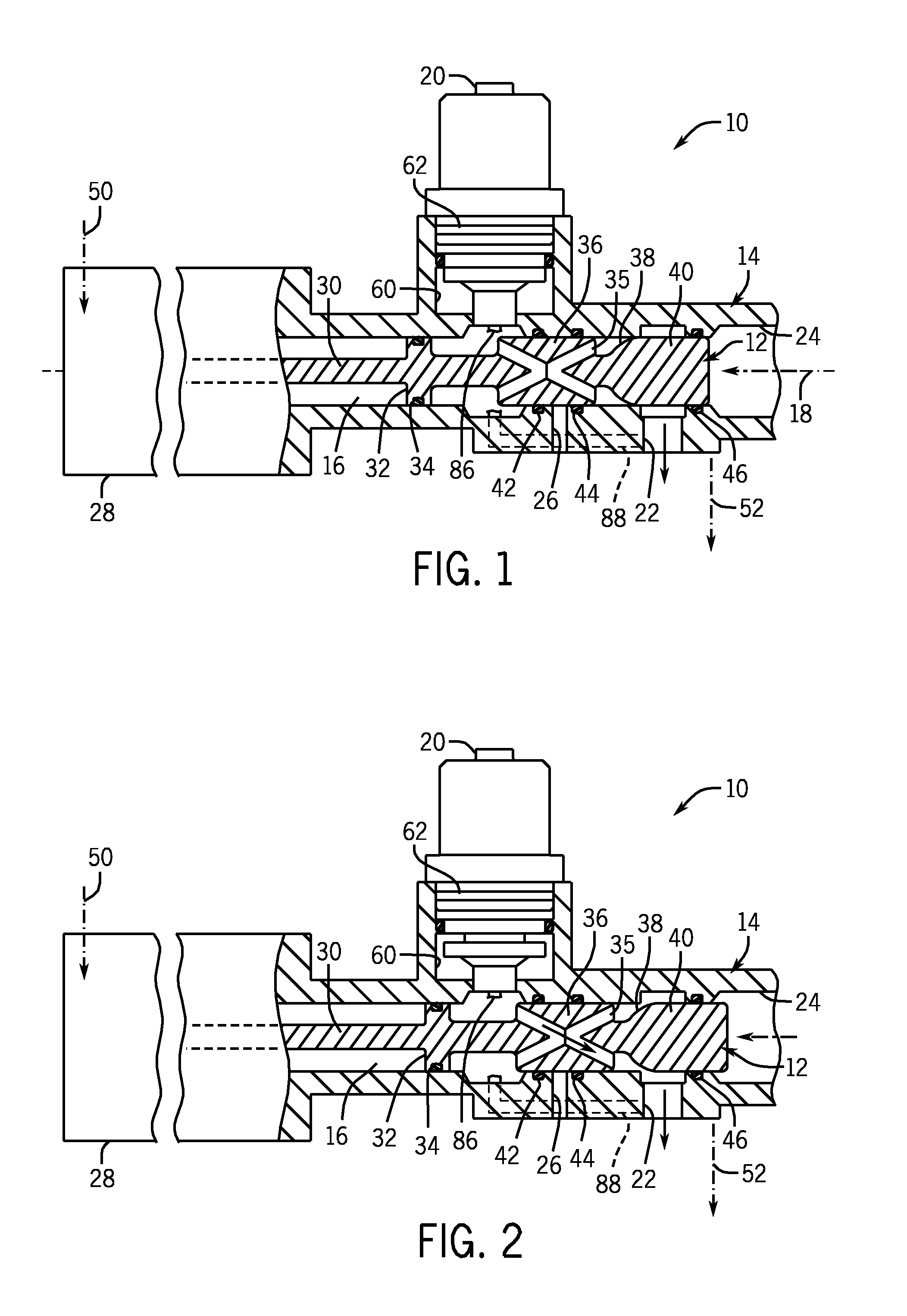
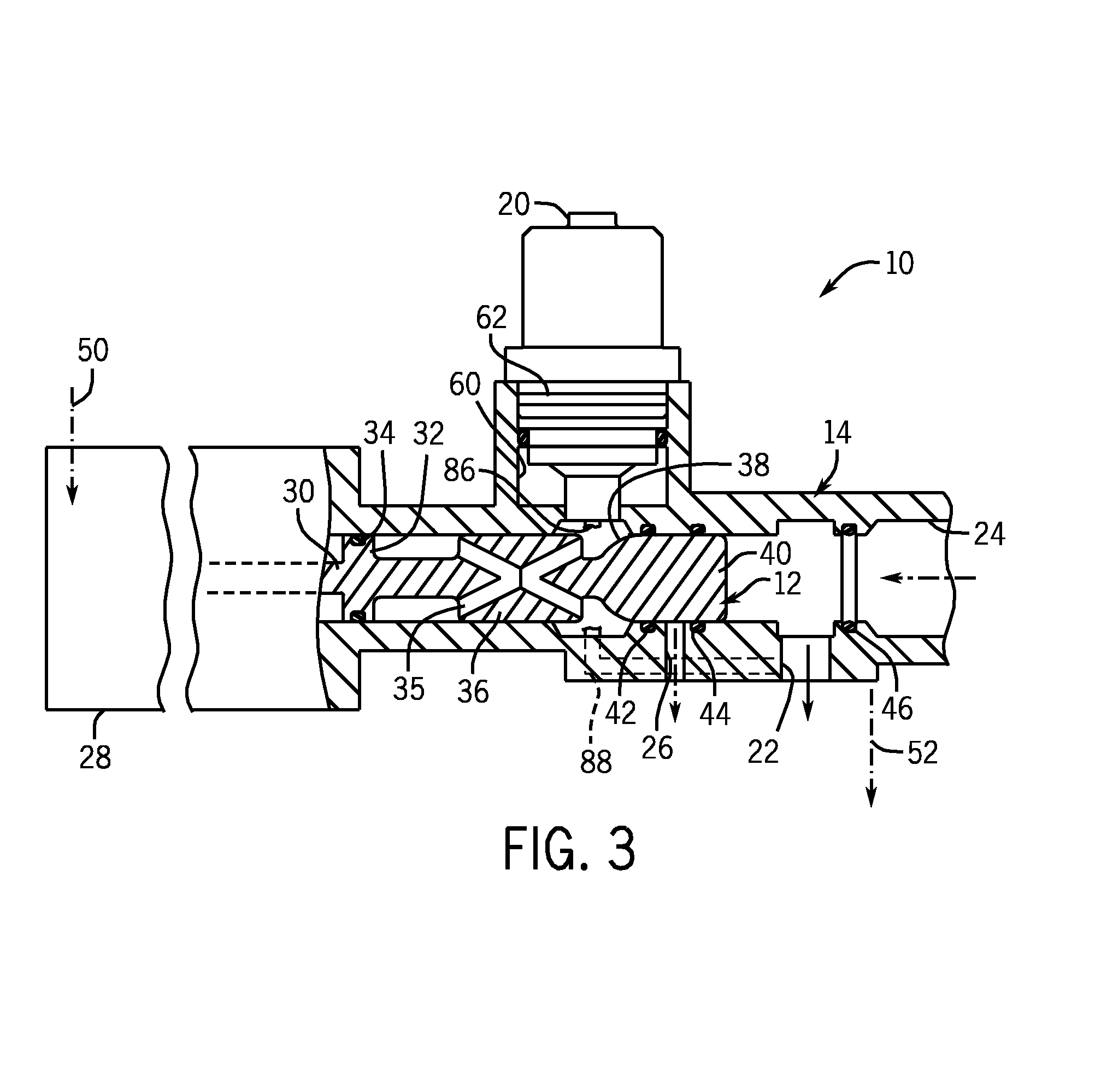
[0033]The present invention provides a unique metering purge valve and a fuel control system of a turbine system which utilizes such a metering purge valve. In a single valve package, the metering purge valve provides metering control of fuel, fuel shut-off and anti-coking purge air functionality directly to turbine without the need for intermediate lines, additional valving or separate fuel metering components. The advantages of the metering purge valve and fuel control system are particularly beneficial for dual fuel turbine systems.

[0034]FIGS. 1-3 of the drawings depict the general construction of a metering purge valve 10 according to the present invention in three different states or positions of its spool 12. In the null position shown in FIG. 1, the spool 12 closes off both fuel flow and purge air flow. The valve 10 thus provides tight shut-off of flow, thereby eliminating the need for additional dedicated shut-off or shear valves. In the position shown in FIG. 2, the spool ...


PUM


Abstract

The fuel system of a dual fuel turbine includes a flow control valve having a metering purge valve that in one state directly meters fuel to injectors of the turbine, in another state closes of fuel flow and passes purge air to the injectors and in another state positively closes of flow of both fuel and purge air. The metering purge valve is a pressure compensated spool valve that has a unique cross-ported interchange that passes fuel from the inlet through the spool to the metering edge. The direct metering of the valve to the injectors eliminates the need for additional shut off valves, and if used with a combining valve having an integral distributor section metering fuel to multiple injectors, the need for a separate flow divider is also eliminated. The valve can be actively cooled by dedicated coolant lines or lines shared with other flow control components such as additional metering valves for either the primary or secondary fuel.

Description

CROSS-REFERENCE TO RELATED APPLICATION(S)[0001]This application claims benefit to U.S. provisional application Ser. No. 60 / 939,980 filed May 24, 2007.STATEMENT OF FEDERALLY SPONSORED RESEARCH OR DEVELOPMENT[0002]Not applicable.BACKGROUND OF THE INVENTION[0003]1. Technical Field[0004]The present invention relates to valves, and in particular, to valves for use with turbine engines.[0005]2. Description of the Related Art[0006]Turbine engines have a set of rotating turbine blades that compress air into the combustion area where fuel is injected and ignited. Combustion of the fuel turns a downstream set of blades from which energy is extracted and which can also be used to drive the compressor blades.[0007]The combustion area of the turbine can be divided by and contained in combustion cans. There are anywhere from six to eighteen such cans in the large turbine systems used to generate power. Each can has a burner to ignite the fuel as well as injectors for injecting the fuel into the c...

Claims


Application Information

Patent Timeline
IPC IPC(8): F02C9/00F02G3/00
CPCF02C7/232F23K5/18F05D2260/602Y10T137/4259Y10T137/86879
Inventor JANSEN, HARVEY B.MCELRATH, SCHUYLER V.
Owner JANSENS AIRCRAFT SYST CONTROLS
Why Eureka
Try Eureka