
Transceiver and method for high-speed auto-compensating quantum cryptography

a quantum cryptography and transmission method technology, applied in the direction of electromagnetic transceivers, digital transmission, instruments, etc., can solve the problems of insufficient security, most currently used cryptography methods, and inability to strictly provide security,

Active Publication Date: 2012-02-14
ELECTRONICS & TELECOMM RES INST
View PDF6 Cites 6 Cited by
  • Summary
  • Abstract
  • Description
  • Claims
  • Application Information

AI Technical Summary

Benefits of technology

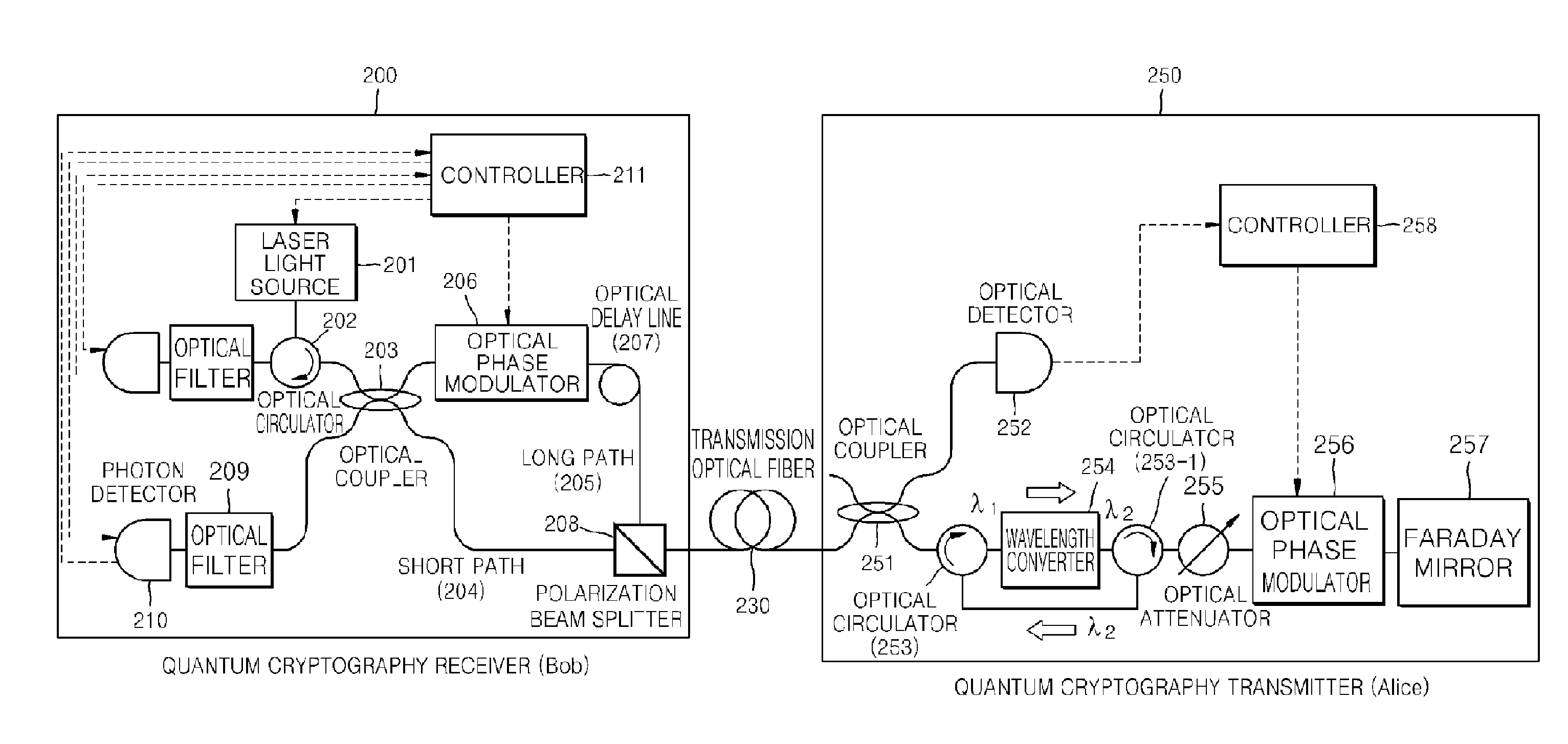
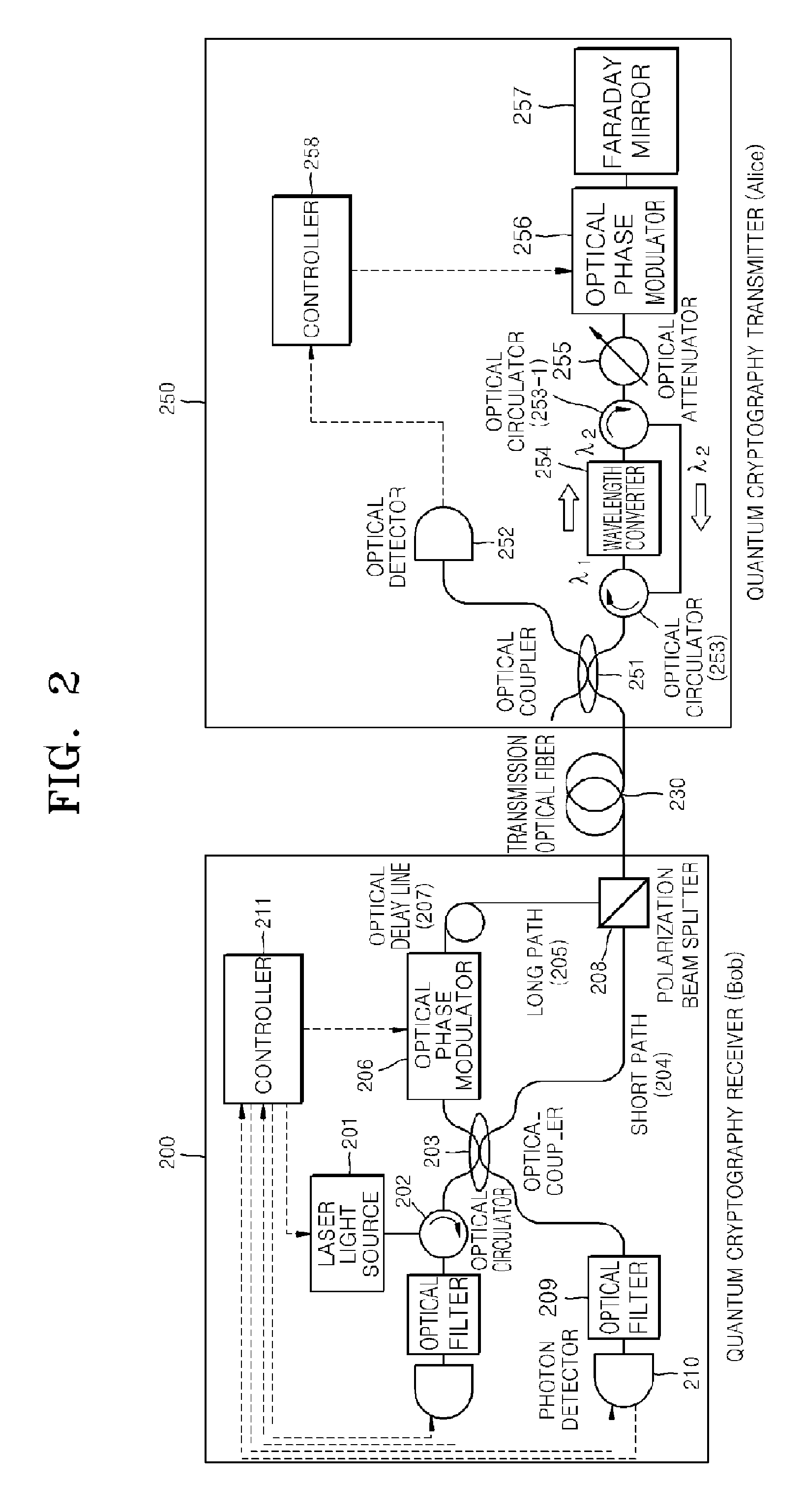
[0014]As described above, a high-speed auto-compensating quantum cryptography system according to the present invention can include a quantum cryptography transmitter including a wavelength converter and a quantum cryptography receiver including an optical filter removing an optical pulse signal caused by Rayleigh scattering. Thus, a limit of a transmission rate caused by the Rayleight scattering of an optical fiber can be overcome.

Problems solved by technology

To achieve such an objective, cryptography must be accurately deciphered by the group using cryptography as a security measure while not allowing the information to be deciphered by a third party.
However, most currently used cryptography methods, such as RSA technology, do not strictly provide security since such technologies are based on conditional security that is substantially difficult to be solved.
A physical natural phenomenon, but not a mathematical technique, is used as a system to prevent tapping since converting a signal during a communication session is useless.

Method used


Image

  • Transceiver and method for high-speed auto-compensating quantum cryptography
  • Transceiver and method for high-speed auto-compensating quantum cryptography
  • Transceiver and method for high-speed auto-compensating quantum cryptography

Examples


Embodiment Construction

[0024]Hereinafter, preferred embodiments of the present invention will be described with reference to the attached drawings.

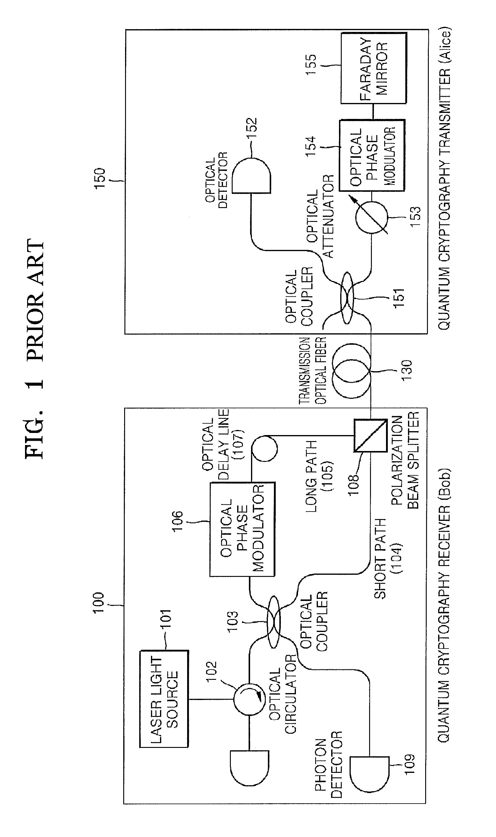
[0025]FIG. 1 is a view illustrating a configuration of an auto-compensating quantum cryptography system according to an embodiment of the previous (or prior) invention.

[0026]The auto-compensating quantum cryptography system is a two-way communication system feeding back an optical signal from a quantum cryptography receiver to a quantum cryptography transmitter, then back to the quantum cryptography receiver, so as to detect a quantum signal.

[0027]In more detail, a quantum cryptography receiver 100 generates an optical pulse through a laser light source 101, and the optical pulse passes through an optical circulator 102 and is split into two optical pulses, i.e., an optical pulse advancing through a short path 104 and an optical pulse advancing through a long path 105, by an optical coupler 103.

[0028]The optical pulse advancing through the long path 105 is inpu...


PUM


Abstract

Provided are an auto-compensating quantum cryptography transceiver and method of transmitting a quantum cryptography key at a high speed. A quantum cryptography transmitter includes a wavelength converter, an optical attenuator, an optical phase modulator, and a Faraday mirror. A quantum cryptography receiver includes a polarization beam splitter, an optical coupler, an optical filter, and a photon detector. Thus, a limit of a transmission rate caused by Rayleigh scattering of an optical fiber can be overcome.

Description

TECHNICAL FIELD[0001]The present invention relates to a transceiver and a method for communicating in quantum cryptography, and more particularly, to a transceiver and a method for overcoming an effect of Rayleigh scattering of an optical fiber and increasing a transmission rate in optical fiber-based auto-compensating quantum cryptography technology.BACKGROUND ART[0002]With the sudden popularity of the Internet, many important tasks involving financial transactions, information exchange, etc, are performed in a computer network. Security when communicating in computer networks is a major concern that has to be attended to.[0003]As such, cryptography allows only a specific group to share information and prohibits other parties other than the specific group communicating to access the contents of the information so as to secure communication. To achieve such an objective, cryptography must be accurately deciphered by the group using cryptography as a security measure while not allowi...

Claims


Application Information

Patent Timeline
Patent Type & Authority Patents(United States)
IPC IPC(8): H04B10/04
CPCH04B10/30H04L9/0858G06F15/00H04B10/40H04B10/85
Inventor YOUN, CHUN JUNOH, TAE GONHONG, JONG CHEOLKIM, HEON OHZYUNG, TAEHYOUNG
Owner ELECTRONICS & TELECOMM RES INST
Learn More