Techniques for varying phase shifts in periodic signals

a phase shift and periodic signal technology, applied in pulse generators, pulse manipulation, pulse techniques, etc., can solve problems such as cdr circuits getting caught in dead zones and incorrect data sampling of cdr circuits

Active Publication Date: 2012-02-21
ALTERA CORP
View PDF9 Cites 12 Cited by
  • Summary
  • Abstract
  • Description
  • Claims
  • Application Information

AI Technical Summary

Benefits of technology

[0004]According to some embodiments, a circuit includes a phase detection circuit and a phase change circuit. The phase detection circuit compares a phase of a first periodic signal to an input signal to generate a gain signal. The phase change circuit provides phase shifts to the first periodic signal in first and second directions when the gain signal has a first value. The phase change circuit increases phase shifts p

Problems solved by technology

Periodic jitter in the data or in the reference frequency signal may cause the CDR circuit to get caught

Method used


Image

  • Techniques for varying phase shifts in periodic signals
  • Techniques for varying phase shifts in periodic signals
  • Techniques for varying phase shifts in periodic signals

Examples


Embodiment Construction

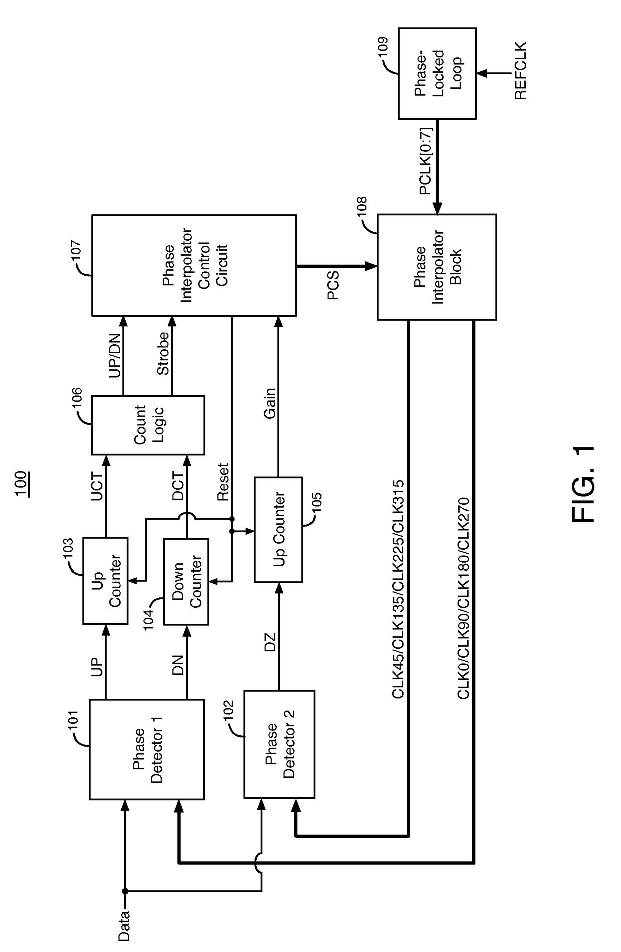
[0013]FIG. 1 illustrates an example of a clock and data recovery (CDR) circuit 100, according to an embodiment of the present invention. CDR circuit 100 includes phase detector circuit 101, phase detector circuit 102, up counter circuit 103, down counter circuit 104, up counter circuit 105, count logic circuitry 106, phase interpolator control circuit 107, phase interpolator circuit block 108, and phase-locked loop circuit 109.

[0014]CDR circuit 100 is typically fabricated in an integrated circuit such as, for example, an application specific integrated circuit (ASIC), a field programmable gate array (FPGA), a programmable logic device (PLD), a memory integrated circuit, a processor or controller integrated circuit, an analog integrated circuit, etc.

[0015]Phase-locked loop (PLL) circuit 109 generates a set of 8 periodic digital clock signals PCLK[0:7] that have the same frequency in response to a reference clock signal REFCLK. PLL 109 can be a digital or an analog PLL. PLL 109 can ge...


PUM


Abstract

A circuit includes a phase detection circuit and a phase change circuit. The phase detection circuit compares a phase of a first periodic signal to an input signal to generate a gain signal. The phase change circuit provides phase shifts to the first periodic signal in first and second directions when the gain signal has a first value. The phase change circuit increases phase shifts provided to the first periodic signal in the first direction in response to the gain signal changing from the first value to a second value. The phase change circuit provides phase shifts to the first periodic signal in the second direction when the gain signal has the second value that are smaller than the phase shifts provided to the first periodic signal in the first direction when the gain signal has the second value.

Description

BACKGROUND OF THE INVENTION[0001]The present invention relates to electronic circuits, and more particularly, to techniques for varying phase shifts in periodic signals.[0002]Many modern digital data systems transmit high-speed data without a clock signal. A receiver that receives the transmitted data generates a clock signal from a reference frequency signal using a phase-locked loop. The receiver then phase-aligns the clock signal to the transitions in the data using a clock and data recovery (CDR) circuit.[0003]Periodic jitter in the data or in the reference frequency signal may cause the CDR circuit to get caught in a dead-zone. When the CDR circuit is caught in a dead-zone, the CDR circuit fails to adjust the phase of the recovered clock signal to the appropriate phase in response to the transitions of the input data signal. The CDR circuit may sample incorrect data when the CDR circuit is caught in a dead-zone. Therefore, it would be desirable to provide a CDR circuit that doe...

Claims


Application Information

Patent Timeline
IPC IPC(8): H03K23/00
CPCH03K5/135H03K2005/00286
Inventor OOI, TENG CHOWLEE, ENG HUATCHAI, CHUAN KHYEKOK, YEW FATT EDWINSHUMARAYEV, SERGEY
Owner ALTERA CORP
Why Eureka
Try Eureka