Optical fiber

a technology of optical fiber and fiber, applied in the field of optical fiber, can solve the problems of inability to easily transmit a large amount of information, loss of transmission, exponential fashion, etc., and achieve the effect of wide transmission band and improved bending characteristics

Active Publication Date: 2012-02-21
SHIN ETSU CHEM IND CO LTD
View PDF12 Cites 1 Cited by
  • Summary
  • Abstract
  • Description
  • Claims
  • Application Information

AI Technical Summary

Benefits of technology

[0016]In view of the above-described prior art, the present invention aims to provide an optical fiber having MFD conforming to G652 standard (preferably 9 μm or above), improved bending characteristics, as well as providing an optical fiber capable of operating in a single mode at 1310 nm and having a wide transmission band.

Problems solved by technology

Such electric cables, however, have a narrow band and so are easily affected by the electromagnetic wave noise, and so cannot easily transmit a large amount of information.
This is because if optical fibers widely different in MFD are connected to each other, it would cause transmission loss.
However as the bending radius becomes small, the ratio of leak of unpropagated light from the core increases in an exponential fashion, to cause transmission loss.
However, connection loss is large when an optical fiber having MFD of about 6 μm is connected to an optical fiber having MFD of about 10 μm, and so the main line and the user line should operate in single mode optical fiber systems separate from each other.
Laser optical sources and optical receivers used in the wavelength of 1300 nm band are comparatively expensive, and so cheaper light emitting diodes (LED) and a surface emitting lasers (VCSEL) in the 850 nm band are often used.

Method used


Image

  • Optical fiber
  • Optical fiber
  • Optical fiber

Examples


embodiment example 1

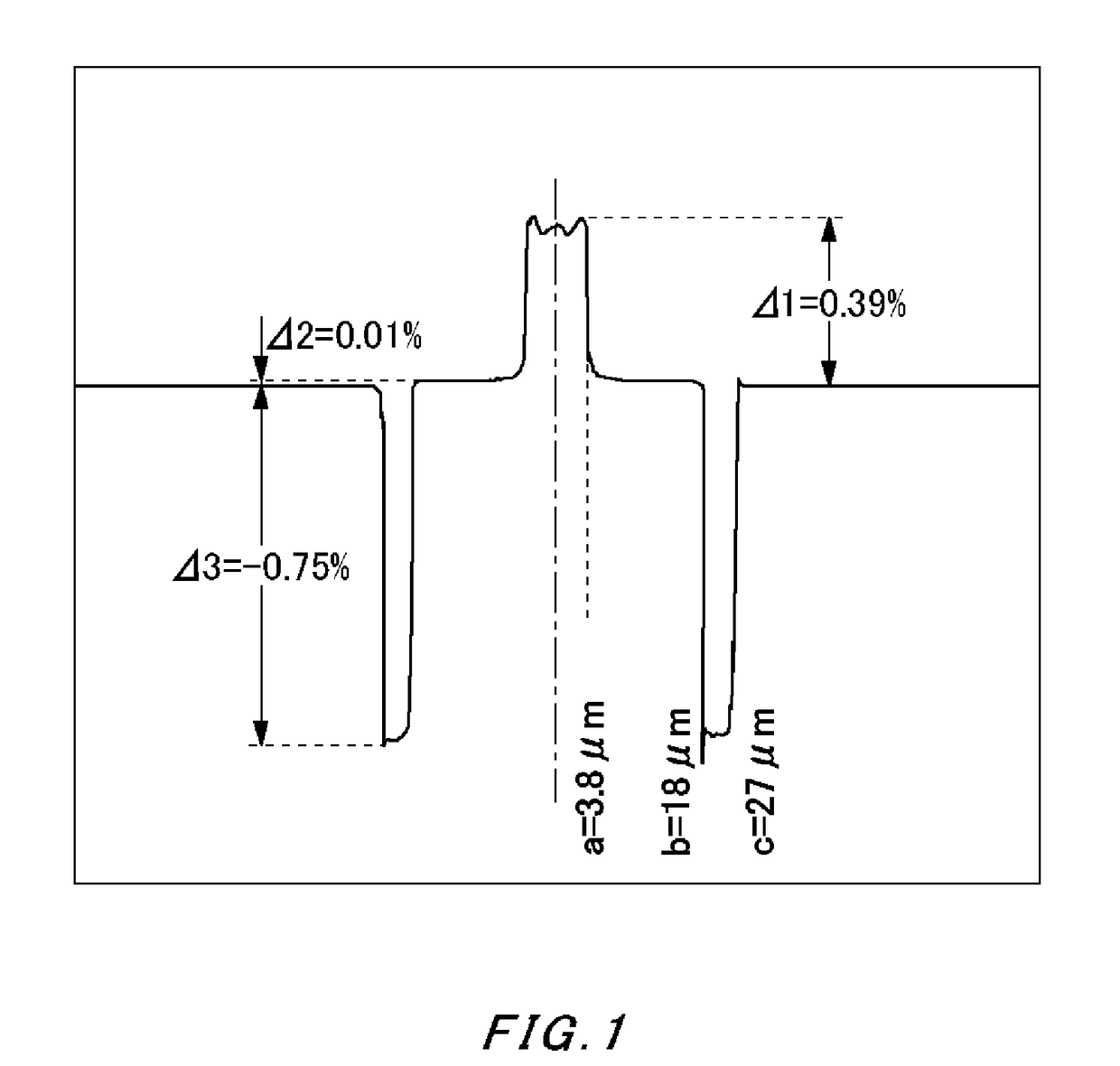
[0028]FIG. 1 shows a refractive index distribution of an optical fiber manufactured in the present Embodiment Example 1.

[0029]First, a first core shown in the drawing is manufactured using a VAD method, which is then stretched into a desired diameter to produce a core material, to which a second core is provided at an exterior of the core material. Further thereon, fluorine is added to form a third core having a refractive index lower than a silica level, onto which, a clad is added, to manufacture an optical fiber base material. This base material is drawn to create an optical fiber having a cladding diameter of 125 μm, which is then coated with urethane acrylate, thereby obtaining an optical fiber wire having a diameter of 250 μm.

[0030]In this optical fiber, the radius of the first core “a” is 3.8 μm, the radius of the second core “b” is 18 μm, and the radius of the third core “c” is 27 μm (the third core having a smaller refractive index). Moreover, the maximum Δ1 of the specific...

embodiment example 2

[0034]A surface of the optical fiber base material manufactured in Embodiment Example 1 is scraped off, which is then drawn to manufacture an optical fiber having a cladding diameter of 125 μm, which is then coated with urethane acrylate, thereby obtaining an optical fiber wire having a diameter of 250 μm.

[0035]The specific refractive index differences Δ1, Δ2, and Δ3 for the respective cores of the manufactured optical fiber are the same as those in Embodiment Example 1, except that the radius of each core is 1.15 times larger than in the case of Embodiment Example 1. Specifically, the radius of the first core “a” is 4.4 μm, the radius of the second core “b” is 21 μm, and the radius of the third core “c” is 31 μm.

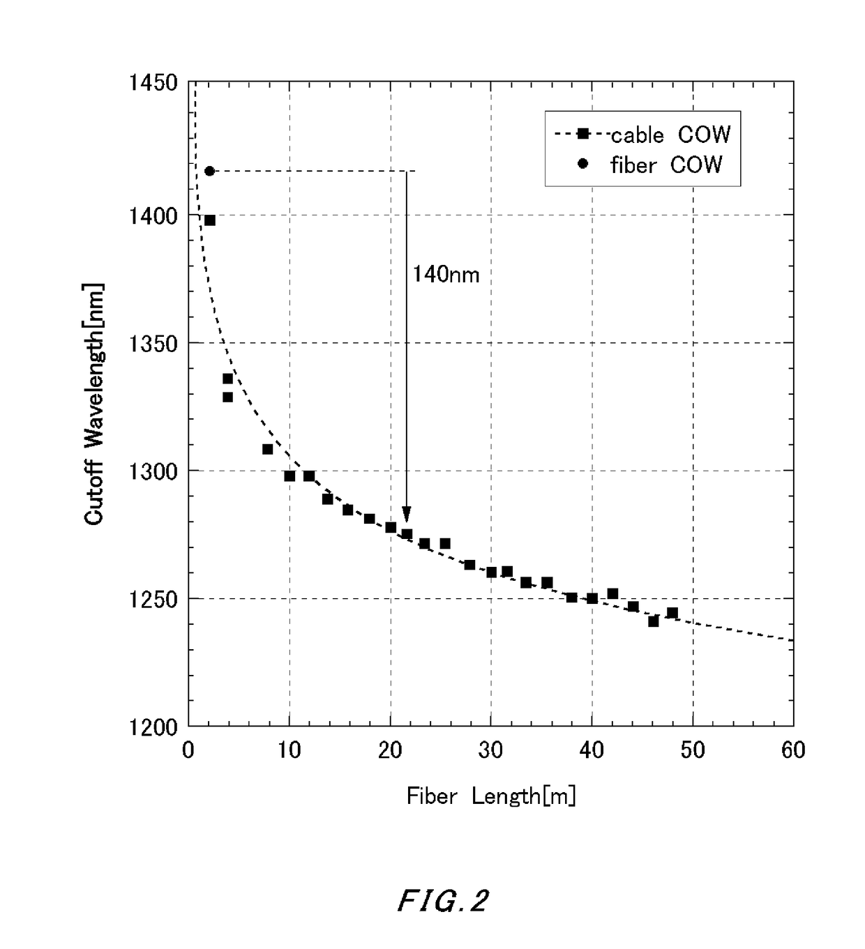
[0036]FIG. 4 shows a relation between the cutoff wavelength and the fiber length. The drawing shows that the fiber cutoff wavelength is 1625 nm and the cable cutoff wavelength is 1430 nm, meaning that the difference therebetween is 195 nm.

[0037]Using an optical fiber having...

embodiment example 3

[0039]A porous glass base material integrating a first core and a second core is manufactured using a VAD method, vitrified into a transparent glass, which is then stretched into a desired diameter to produce a core material. Further thereon, fluorine is added by providing porous glass at an exterior, to form a third core having a refractive index lower than a silica level, onto which, a clad is added, to manufacture an optical fiber base material. FIG. 6 shows a result of measuring the refractive index distribution of the base material using a commercially available preform analyzer.

[0040]This base material is drawn to create an optical fiber having a cladding diameter of 125 μm, which is then coated with urethane acrylate, thereby obtaining an optical fiber wire having a diameter of 250 μm. Thus obtained optical fiber has a diameter smaller than that of the base material while maintaining a similar shape to the shape of the base material, and so its refractive index distribution w...


PUM


Abstract

Provided is an optical fiber including: a first core at a center thereof; a second core adjacent to the first core to cover a circumference of the first core; a third core adjacent to the second core to cover a circumference of the second core; and a cladding adjacent to the third core to cover a circumference of the third core, where conditions of 0.28%≦Δ1≦0.4%, −0.05%≦Δ2≦0.05%, −1.0%≦Δ3≦−0.5%, 3.8 μm≦a≦4.5 μm, 12 μm≦b≦21 μm, and 1.5 μm≦c-b≦10 μm hold, and loss increase resulting when the optical fiber is wound on a mandrel having a diameter of 20 mm is 0.1 dB / turn or smaller at a wavelength of 1625 nm, where Δ1 is a specific refractive index difference of the first core from the cladding refractive index, Δ2 is a specific refractive index difference of the second core from the cladding refractive index, Δ3 is a specific refractive index difference of the third core from the cladding refractive index, “a” is a radius of a boundary between the first core and the second core with respect to a center of the first core, “b” is a radius of a boundary between the second core and the third core with respect to the center of the first core, and “c” is a radius of a boundary between the third core and the cladding with respect to the center of the first core.

Description

[0001]The contents of the following patent application is incorporated herein by reference, NO. 2009-121725 filed on May 20, 2009.BACKGROUND[0002]1. Technical Field[0003]The present invention relates to an optical fiber for optical communication, and particularly relates to an optical fiber suitable as a long distance line and Optical Fiber To The Home (FTTH) having transmission length of some tens of kilometers, and interconnection inside or outside homes in local area networks (LAN).[0004]2. Related Art[0005]Optical fibers are suitable for long distance communication for their wide band characteristics, and are widely used for communication in main lines of a long distance such as some tens of kilometers and above.[0006]On the other hand, with rapid prevalence of the Internet, the amount of information transceived by individual personal computers has also increased dramatically. The widely used technology in this field has been copper electric cables such as a coaxial cable and an...

Claims


Application Information

Patent Timeline
Patent Type & Authority Patents(United States)
IPC IPC(8): G02B6/26
CPCG02B6/0365G02B6/02014G02B6/02266
Inventor OYAMADA, HIROSHI
Owner SHIN ETSU CHEM IND CO LTD
Why Eureka
Try Eureka