Ablation catheter with optically transparent, electrically conductive tip

a catheter and electrode technology, applied in the field of ablation catheters, can solve the problems of inability to obtain real-time information regarding the condition of the treatment site within the body, inability to inform the clinician, irregular heart beating, etc., to minimize damage caused by abrasion of the fiber optics, increase the operative life of the catheter, and minimize the effect of bend or strain

Active Publication Date: 2012-02-28
BIOSENSE WEBSTER INC
View PDF25 Cites 62 Cited by
  • Summary
  • Abstract
  • Description
  • Claims
  • Application Information

AI Technical Summary

Benefits of technology

[0015]Advantageously, the light used to monitor and assess the tissue (or a lesion formed in the tissue) is generally not affected by the portion of the electromagnetic radiation used for ablation. Moreover, the bandwidth used for monitoring and assessing also transmits through blood with minimal attenuations. The fiber optics are used and disposed in the catheter in a manner that avoids contact with tissue, which can increase the operative lifetime of the catheter and minimize damages caused by abrasion to the fiber optics. Furthermore, the alignment plug in the tip electrode secures the fiber optic cables with minimal bend or strain but increased angular coverage, which can minimize fiber optics breakage during assembly and use, as well as reduce nonlinear optical effects caused by orientation of the fiber optics. In addition, the use of fiber optics to emit and receive light is a generally temperature neutral process that adds little if any measurable heat to surrounding blood or tissue.

Problems solved by technology

For certain types of minimally invasive medical procedures, real time information regarding the condition of the treatment site within the body is unavailable.
This lack of information inhibits the clinician when employing catheter to perform a procedure.
This condition in the heart causes abnormal electrical signals, known as cardiac arrhythmias, to be generated in the endocardial tissue resulting in irregular beating of the heart.
The most frequent cause of cardiac arrhythmias is an abnormal routing of electricity through the cardiac tissue.
Furthermore, the ablation process can also cause undesirable charring of the tissue and localized coagulation, and can evaporate water in the blood and tissue leading to steam pops.
Clearly, post ablation evaluation is undesirable since correction requires additional medical procedures.
Biochemical differences between ablated and normal tissue can result in changes in electrical impedance between the tissue types.
Measuring impedance merely provides data as to the location of the tissue lesion but does not give qualitative data to evaluate the effectiveness of the lesion.
This technique, however, measures the success or lack thereof from each lesion, and yields no real-time information about the lesion formation.
There are available many transparent, electrical conductors but each has its limitations.
The challenge had been to deposit nanotubes in a layer thin enough to be optically transparent while maintaining electrical contract through the layer.

Method used


Image

  • Ablation catheter with optically transparent, electrically conductive tip
  • Ablation catheter with optically transparent, electrically conductive tip
  • Ablation catheter with optically transparent, electrically conductive tip

Examples


Embodiment Construction

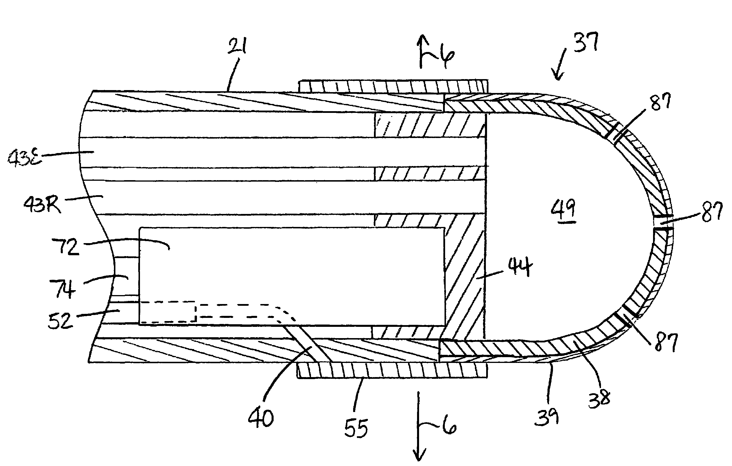
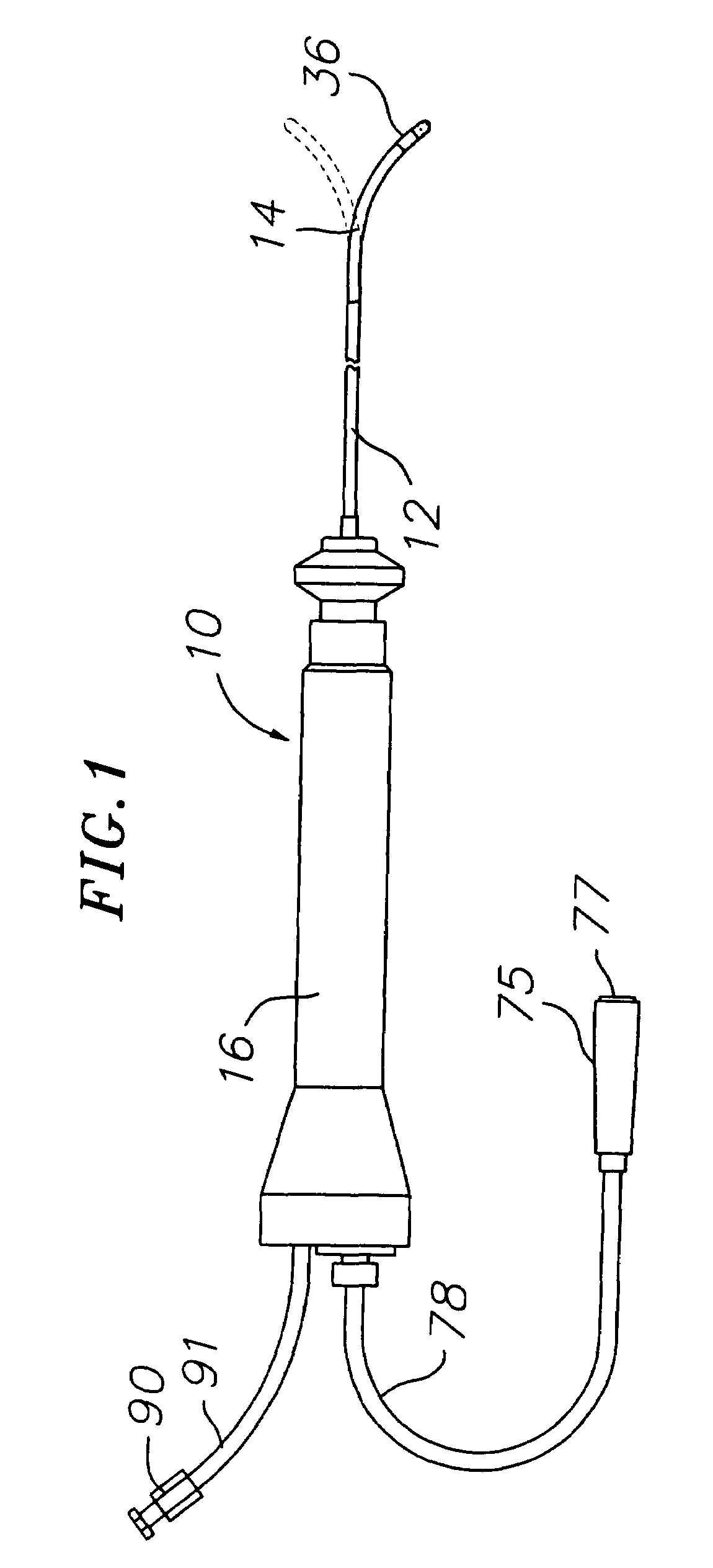
[0027]As shown in FIGS. 1-6, a catheter 10 of the present invention comprises an elongated catheter body 12 having proximal and distal ends, a deflectable (uni- or bi-directionally) intermediate section 14 at the distal end of the catheter body 12, a tip section 36 at the distal end of the intermediate section, and a control handle 16 at the proximal end of the catheter body 12.

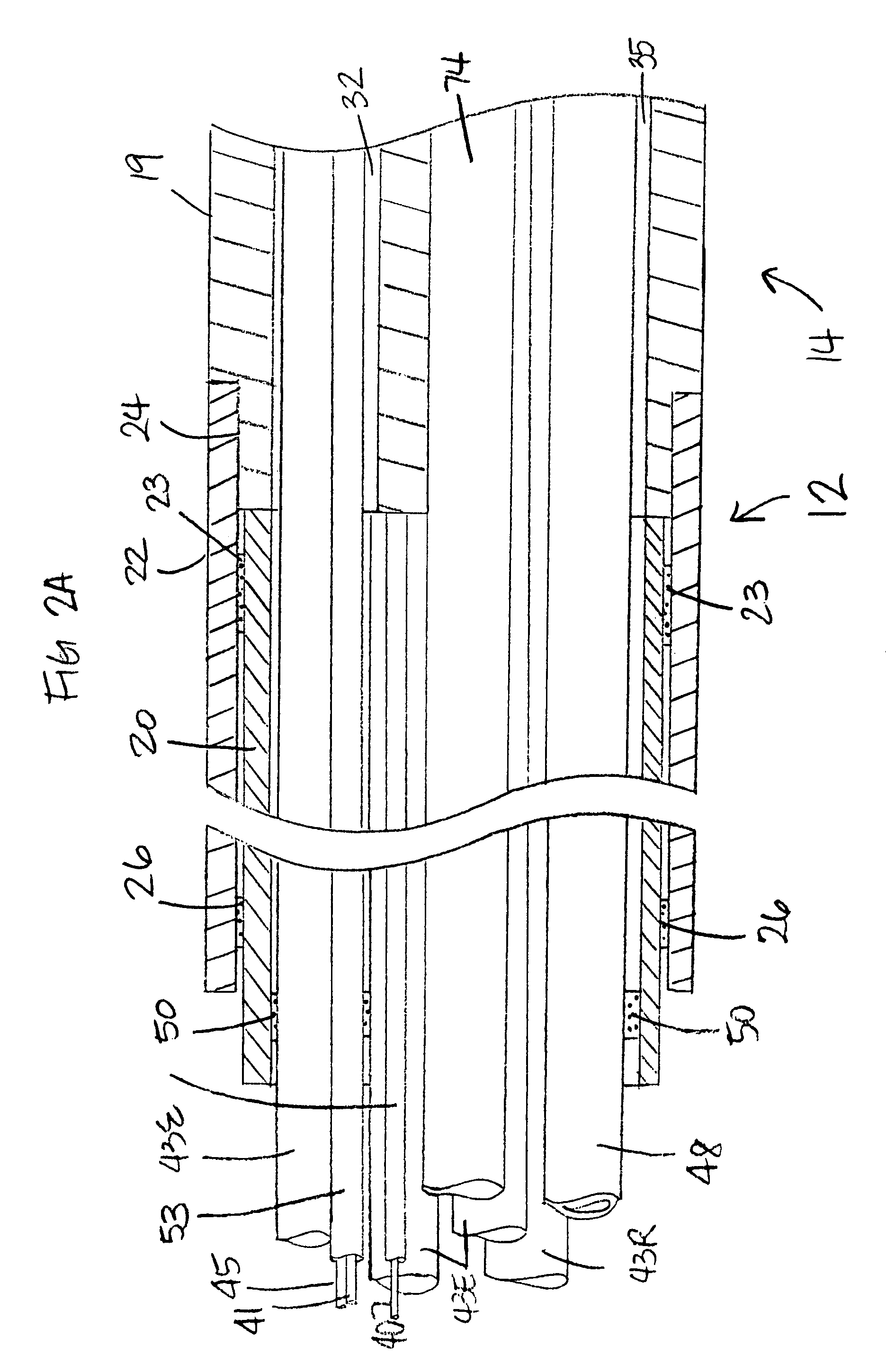
[0028]With additional reference to FIGS. 2A and 2B, the catheter body 12 comprises an elongated tubular construction having a single, axial or central lumen 18. The catheter body 12 is flexible, i.e., bendable, but substantially non-compressible along its length. The catheter body 12 can be of any suitable construction and made of any suitable material. A construction comprises an outer wall 22 made of an extruded plastic. The outer wall 22 may comprise an imbedded braided mesh of stainless steel or the like to increase torsional stiffness of the catheter body 12 so that, when the control handle 16 is rotated...


PUM

PropertyMeasurementUnit
wall thicknessaaaaaaaaaa
outer diameteraaaaaaaaaa

Abstract

A catheter enables real-time light measurements, for example, without limitation, diffuse reflectance, fluorescence, etc., from biological materials, such as tissue (including blood), while performing RF ablation. The catheter tip design isolates illumination and collection paths such that light exits the catheter tip and travels through the tissue of interest (e.g., cardiac tissue or blood) before returning to the catheter tip. Such a design advantageously avoids saturation of the optical detector, and ensures diffusion of the illumination light within the medium of interest. The catheter has a catheter body and a tip electrode. The tip electrode has an exterior shell, an inner layer of diffuse material and a hollow cavity, wherein the inner layer is configured to transmit light outside the tip electrode to a tissue via a set of illumination openings in the shell wall and the hollow cavity is configured to receive light from the tissue via a set of collection openings in the shell wall and the inner layer. An inner surface of the inner layer has a reflective coating to isolate light injected into the inner layer from light collected in the hollow cavity. There are a first optical waveguide extending between the catheter body and the tip electrode to inject light into the inner layer and illuminate the tissue, and a second optical waveguide extending between the catheter body and the tip electrode to collect the recaptured light in the hollow cavity.

Description

FIELD OF INVENTION[0001]The present invention relates to ablation catheters, and in particular to ablation catheters with optical monitoring of tissue.BACKGROUND[0002]For certain types of minimally invasive medical procedures, real time information regarding the condition of the treatment site within the body is unavailable. This lack of information inhibits the clinician when employing catheter to perform a procedure. An example of such procedures is tumor and disease treatment in the liver and prostate. Yet another example of such a procedure is surgical ablation used to treat atrial fibrillation. This condition in the heart causes abnormal electrical signals, known as cardiac arrhythmias, to be generated in the endocardial tissue resulting in irregular beating of the heart.[0003]The most frequent cause of cardiac arrhythmias is an abnormal routing of electricity through the cardiac tissue. In general, most arrhythmias are treated by ablating suspected centers of this electrical m...

Claims


Application Information

Patent Timeline
Patent Type & Authority Patents(United States)
IPC IPC(8): A61B18/14
CPCA61B5/14542A61B5/1459A61B18/1492B82Y5/00B82Y30/00A61B2017/0088A61B2018/00107A61B2018/00125A61B2018/00351A61B2018/00815A61B2018/00821A61B2019/5206A61B2019/5217A61B2019/5231A61B2019/5276A61B2090/373A61B2090/3614A61B2090/306A61B2090/378
Inventor BEECKLER, CHRISTOPHERLIEBER, CHAD ALLENSHARAREH, SHIVA
Owner BIOSENSE WEBSTER INC
Why Eureka
Try Eureka