Device and method for detecting direction of polarization of ferroelectric material

a technology of ferroelectric material and polarization direction, which is applied in the direction of ferroelectric carrier recording, instrumentation, reradiation, etc., can solve the problems of difficult to measure the inner polarization of the ferroelectric, the theoretical limit of the storage density of magnetic recording, and the current most widely used recording method for recording information, etc., to suppress the influence of noise and high signal detection sensitivity

Inactive Publication Date: 2012-03-06
PIONEER CORP
View PDF5 Cites 2 Cited by
  • Summary
  • Abstract
  • Description
  • Claims
  • Application Information

AI Technical Summary

Benefits of technology

[0006]Therefore, the present invention has been made in view of the above circumstances, and it is an object of the present invention to provide a device and method for detecting the direction of polarization of a ferroelectric material, which can maintain high signal detection sensitivity by suppressing the influence of noise generated when an alternating electric field having a relatively high frequency has been applied to the ferroelectric material.Measure Taken to Solve the Problem

Problems solved by technology

The storage density of magnetic recording, which is currently the most widely used as means for recording information, is approaching the theoretical limit.
However, it is difficult to measure inner polarizations of the ferroelectric, i.e., to read information recorded in the ferroelectric since the inner polarizations of the ferroelectric are shielded by surface charges on the ferroelectric such as electrons or ions attached to the surface of the ferroelectric.

Method used


Image

  • Device and method for detecting direction of polarization of ferroelectric material
  • Device and method for detecting direction of polarization of ferroelectric material
  • Device and method for detecting direction of polarization of ferroelectric material

Examples


first embodiment

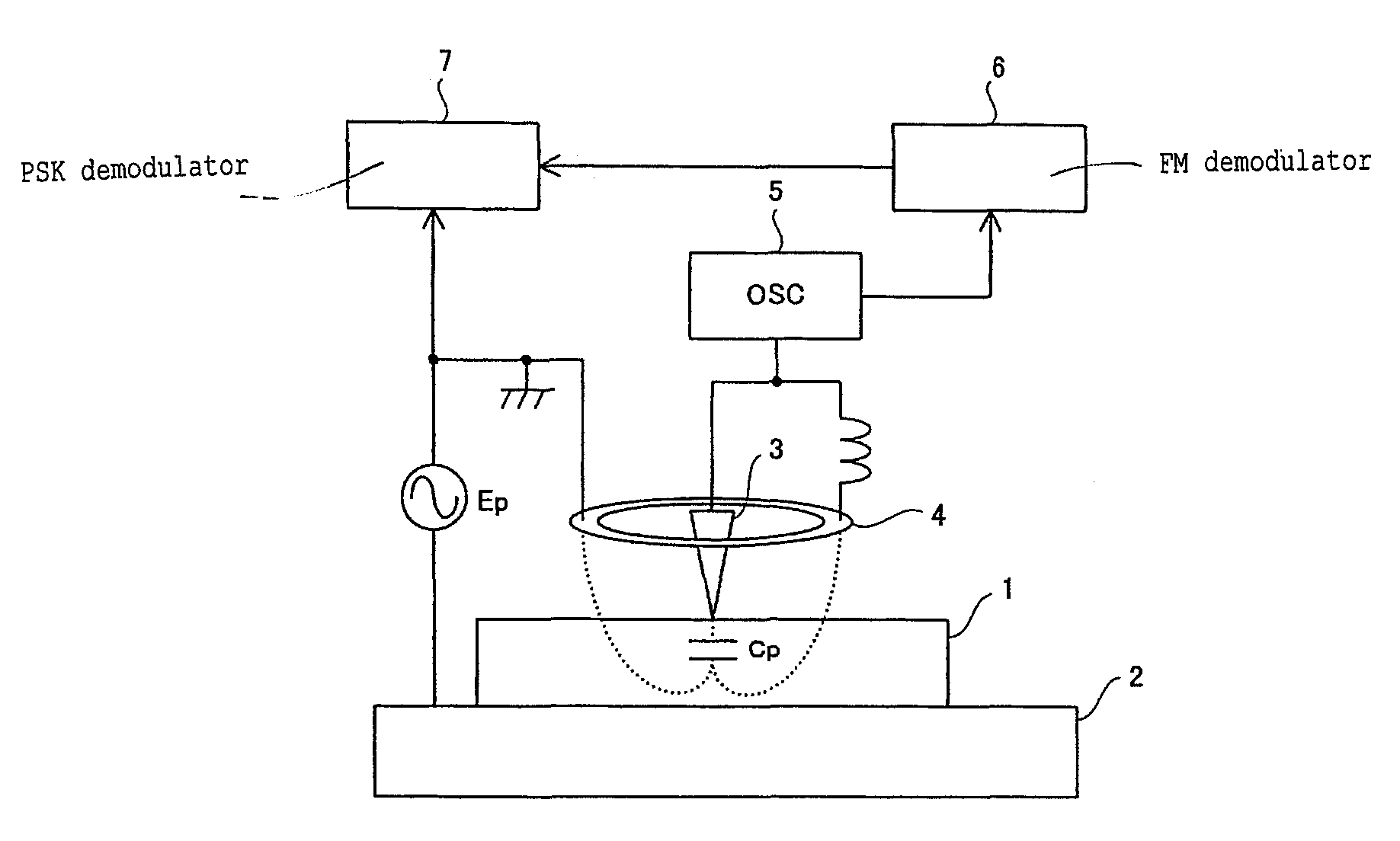
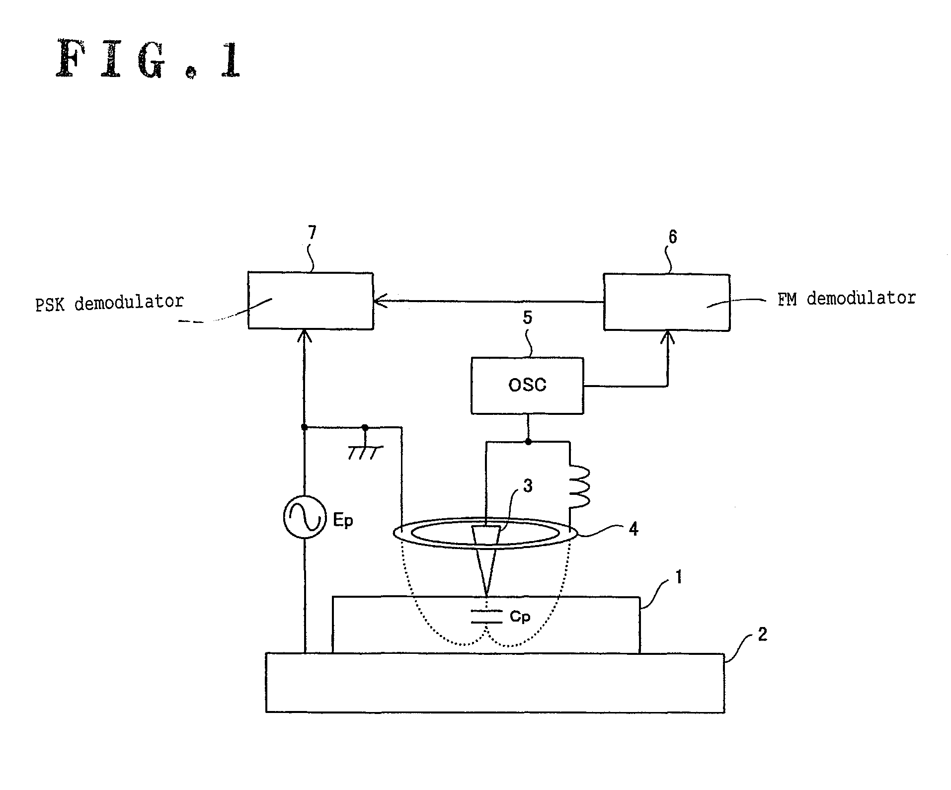
[0031]FIG. 2 is a block diagram illustrating a configuration of a device for detecting the direction of polarization of a ferroelectric material according to the present invention. A medium 10 is a measurement target of the polarization direction detection device of the present invention and includes, for example, a ferroelectric material such as LiTaO3. The direction of polarization of the medium 10 can be changed by applying an electric field greater than a coercive electric field to the medium 10 and data can be recorded on the medium 10 by determining the direction of polarization of the medium 10 in association with the data. That is, the polarization direction detection device of the present invention may be used as a reproduction device that reproduces data recorded on the medium 10 by detecting the polarization direction of the ferroelectric material. The direction of polarization of the medium 10 is reflected in the nonlinear dielectric constant of the ferroelectric materia...

second embodiment

[0058]FIG. 7 illustrates a second embodiment of the device for detecting the direction of polarization of a ferroelectric material of the present invention. The detection device of the second embodiment is different from the first embodiment with regard to a signal that is subjected to correction by the cancel signal V5(t). That is, in the detection device of the first embodiment, the subtractor 40 is provided downstream of the FM demodulator 30 and the frequency detection signal V2(t) output from the FM demodulator 30 is subjected to correction by the cancel signal V5(t). In this embodiment, a signal correction process is performed in a frequency control loop of an FM demodulator 30. That is, in the detection device of this embodiment, a subtractor 40 is provided downstream of a controller 35 which is provided in the frequency control loop of the FM demodulator 30 and a control signal from the controller 35 and a cancel signal V5(t) from a signal generator 70 are input to a subtrac...

third embodiment

[0059]FIG. 8 illustrates a third embodiment of the device for detecting the direction of polarization of a ferroelectric material of the present invention. The detection device of the third embodiment is different from the first and second embodiments with regard to the principle of detection of the polarization direction of the medium 10. That is, the detection device of the first and second embodiments converts a change of the capacitance Cp of the capacitor C formed directly below the probe 11 due to application of an alternating electric field into a frequency change using an oscillator which has the capacitor C as a component and demodulates the frequency change using an FM demodulator to detect the polarization direction of the medium 10. The detection device according to this embodiment converts a change of the capacitance Cp into a phase change to detect the polarization direction of the medium 10. Specifically, when compared to the detection device of the first embodiment, ...


PUM


Abstract

A device for detecting polarization direction of a ferroelectric is provided. From a measurement signal provided through a probe disposed in contact with or near the surface of a ferroelectric, a demodulation means generates a detection signal having a signal level corresponding to a capacitance change of the ferroelectric due to application of an alternating electric field to a capacitor component formed in the ferroelectric directly below the probe. A synchronous detection means performs synchronous detection of the detection signal based on a synchronous signal and generates a polarization direction detection signal corresponding to the polarization direction of the ferroelectric. A pseudo-noise signal generation means generates a pseudo-noise signal with the same frequency as that of the electric field signal and a different phase and amplitude therefrom. The demodulation means includes a noise component removal means that removes noise components in the measurement signal through signal arithmetic processing with the pseudo-noise signal.

Description

TECHNICAL FIELD[0001]The present invention relates to a device and method for detecting the direction of polarization of a ferroelectric material.BACKGROUND ART[0002]Recently, demand for a technology for storing a large amount of information at a high speed has increased along with an increase in the amount of information. The storage density of magnetic recording, which is currently the most widely used as means for recording information, is approaching the theoretical limit. Even when vertical magnetic recording is used, it is believed that 1 Tbit / inch2 is the upper storage density limit. On the other hand, a ferroelectric exhibits spontaneous polarization, the direction of which can be reversed by applying an electric field from the outside to the ferroelectric. Accordingly, it is possible to record information by associating corresponding digital data with the direction of polarization of the ferroelectric. In addition, a domain wall of the ferroelectric has a thickness of about...

Claims


Application Information

Patent Timeline
Patent Type & Authority Patents(United States)
IPC IPC(8): G01R27/04
CPCG11B9/02G11B9/06G11B11/08
Inventor TATEISHI, KIYOSHIYABE, TOMOTAKA
Owner PIONEER CORP
Why Eureka
Try Eureka