
Highly buoyant and semi-rigid floating islands

a floating island, high-floating technology, applied in the field of floating islands, can solve the problems of low aesthetic value at locations, difficult or expensive installation of piling-supported bridges, and art floating platforms that also tend to gradually lose buoyancy over time, and achieve low permeability, low-oxygen microbial growth conditions, and promote a range of microbial growth conditions

Active Publication Date: 2012-03-13
FOUNTAINHEAD
View PDF36 Cites 6 Cited by
  • Summary
  • Abstract
  • Description
  • Claims
  • Application Information

AI Technical Summary

Benefits of technology

[0011]The purpose of the invention is to provide highly buoyant and semi-rigid floating platforms that may be used to enable pedestrians and / or vehicles to cross bodies of water, or to treat contaminated water, or to provide wildlife nesting habitat. One advantage of preferred embodiments of the invention is that individual island units can be semi-rigidly connected so as to form a large, highly buoyant floating structure with high and uniform rigidity over the entire top surface. Another advantage of the invention is that open spaces can be designed between the individual units of a multiple-unit structure, and these spaces can be filled with plant bedding pockets, in order to provide a relatively low-cost means for adding plant-growing areas to the structure. For the purposes of this disclosure, the term “semi-rigid” means substantially rigid or rigid to at least some degree or rigid in at least some parts.
[0012]Another advantage of the invention that the interior of the island body may be comprised of zones with different levels of permeability and porosity, in order to promote a range of microbial growing conditions. For example, low permeability zones fabricated from fine-denier, tightly packed fibers would promote low-oxygen microbial growth conditions, while high permeability zones fabricated from coarse-denier, loosely packed fibers would promote high-oxygen microbial growth conditions. This combination of alternating aerobic and anaerobic zones within a single island body is particularly useful for performing certain multiple-step biological treatments. For example, ammonia is converted to inert nitrogen gas by the sequential steps of aerobic conversion of ammonia to nitrite, followed by aerobic conversion of nitrite to nitrate, followed by anoxic conversion of nitrate to nitrogen gas.
[0013]Another advantage of the invention is that the individual blocks of permeable material that make up the interior of the island may be pre-fabricated to standard size, and they may be manufactured so as to have particular buoyancy, permeability and porosity. They may optionally be fabricated wholly or partially from scrap materials that result from island construction or other manufacturing operations. Blocks with different characteristics may be combined within a single island to provide zones of different microbial growing conditions (e.g., aerobic and anaerobic).
[0014]Another advantage of the present invention is that the internal hollow semi-rigid frame of some embodiments may be used to transport water, air, and / or treatment additives (such as pH modifiers and carbon sources) into and through the interior of the permeable island body, thereby enhancing the effectiveness of the island for water quality treatment. In addition, the water and air may be either cooled or heated prior to injection in order to make them more effective for a particular treatment application.
[0015]In a preferred embodiment, the invention is a method of making a floating walkway comprising: providing a internal section that is permeable to water and buoyant in water and that has a top surface, said internal section preferably comprising a bi-cellular polymer foam or a nonwoven polymer matrix that contains at least one buoyant polymer foam inclusion; spraying a two-part foaming polyurethane resin onto and into said top surface to produce a foam layer; spraying a (preferably two-part) polyurea resin on said foam layer to form a top coat that becomes semi-rigid when it cures. Preferably, the method further comprises: adding a dye or pigment to said two-part polyurea resin before it is sprayed. Preferably, the method further comprises: sprinkling aggregate or sand onto said top coat before it has cured. Preferably, the method further comprises: adding a plurality of granular particles to said two-part polyurea resin before it is sprayed.
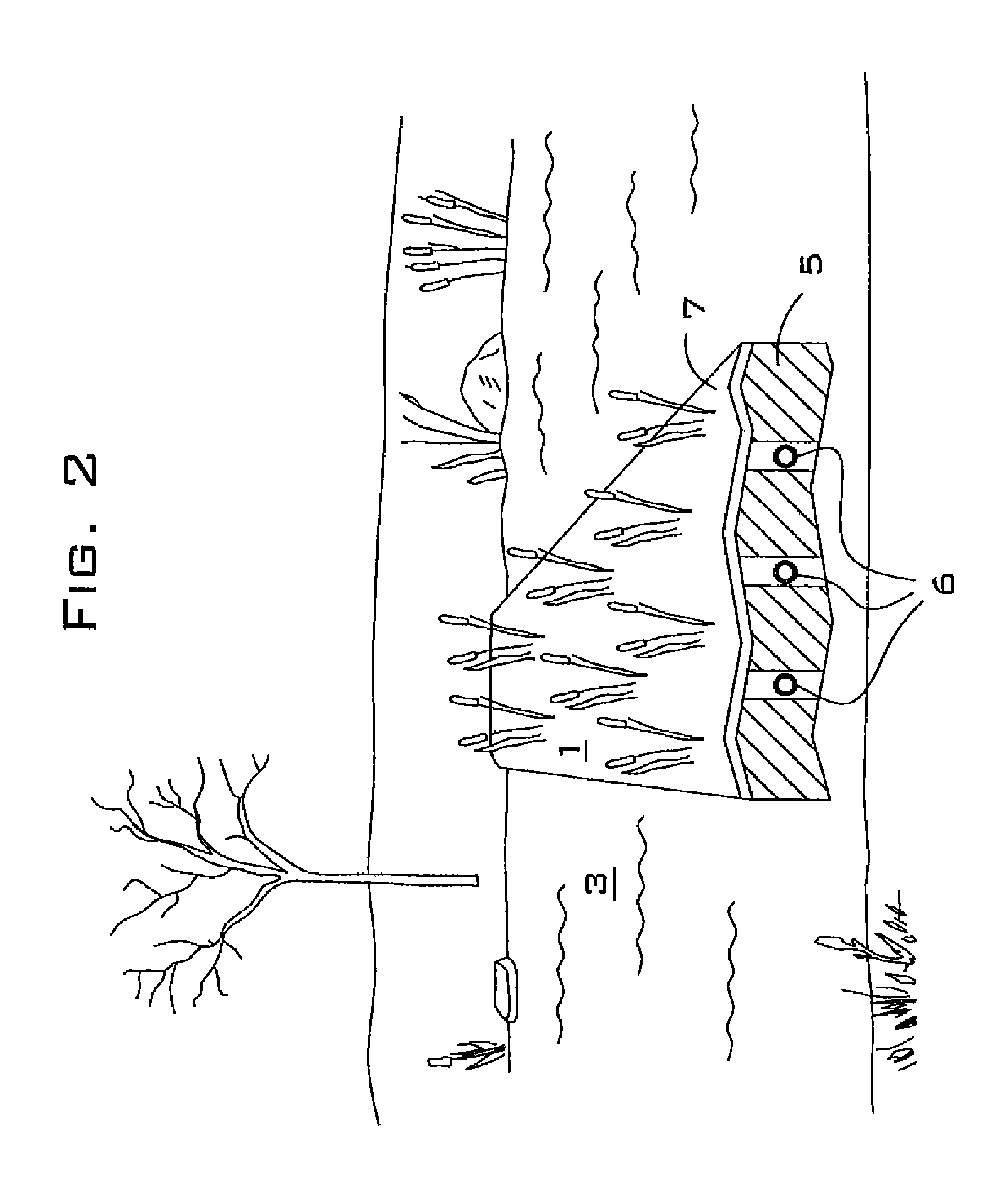
[0016]In another preferred embodiment, the invention is a buoyant walkway comprising: an internal frame comprising semi-rigid members that are attached to one another (preferably at substantially right angles), said internal semi-rigid frame having (preferably substantially rectangular openings); an internal block disposed in each of said rectangular openings, said internal blocks being spaced apart from one another by gaps and forming a top surface and a bottom surface; cured thermoplastic foam disposed in said gaps that attach said internal blocks to said semi-rigid internal frame and to one another; a permeable top layer preferably comprising a nonwoven matrix, an open cell polymer foam or a bi-cellular polymer foam, said permeable top layer being attached to said top surface; and a bottom layer preferably comprising a nonwoven matrix, an open cell polymer foam or a bi-cellular polymer foam, said permeable top layer being attached to said bottom surface. Preferably, each internal block is fabricated from a material selected from the group consisting of: a nonwoven matrix that is comprised of a plurality of polyester fibers or a plurality of polyethylene fibers or a plurality of polypropylene fibers that are intertwined to form a randomly oriented web or blanket; an open-cell foam that is comprised of a thermosetting polymer or a thermoplastic polymer; a bi-cellular polymer foam that is comprised of a thermosetting polymer or a thermoplastic polymer. Preferably, each internal block is fabricated from a combination comprising one or more compressed and bound together items selected from the group consisting of: a plurality of low-density nonwoven matrix pieces; a plurality of high-density nonwoven matrix pieces; a plurality of closed-cell polymer foam pieces; a plurality of bi-cellular foam pieces; and a plurality of open-cell foam pieces. Preferably, each low-density nonwoven matrix piece and / or high-density nonwoven matrix piece is comprised of a plurality of thermosetting fibers or a plurality of thermoplastic fibers. Preferably, each thermosetting fiber is a polyester fiber and each thermoplastic fiber is a polypropylene fiber or a polyethylene fiber. Preferably, adjacent internal blocks have different permeabilities. Preferably, adjacent internal blocks have different buoyancies.

Problems solved by technology

Floating walkways and roadways may also be preferable to conventional bridges at locations where the water depth or bottom materials make pile-supported bridges difficult or expensive to install.
As a result of the materials and methods that are employed to construct background art floating platforms, these structures have low aesthetic value at locations where natural appearance is important.
Background art floating platforms also tend to gradually lose buoyancy over time due to factors such as water absorption into the foam flotation, loss of flotation due to impact, ice damage, or waterlogging of the top surface.
Some water bodies experience contamination in the form of excess nutrient inflows from sources such as crop fertilizer, wastewater facility effluent and livestock waste runoff.
These excess nutrients, which may include ammonia, nitrate, and phosphate, can promote algae growth and be toxic to fish, wildlife, and humans.
Background art floating treatment platforms do not have the combination of high buoyancy, rigidity, natural appearance, and high treatment efficiency.

Method used


Image

  • Highly buoyant and semi-rigid floating islands
  • Highly buoyant and semi-rigid floating islands
  • Highly buoyant and semi-rigid floating islands

Examples


Embodiment Construction

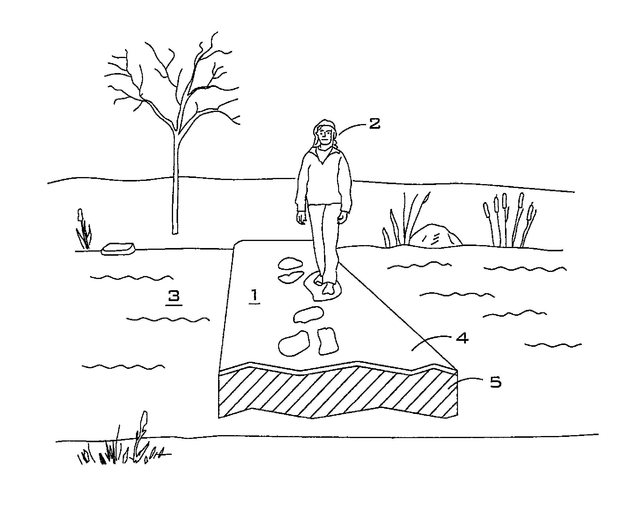
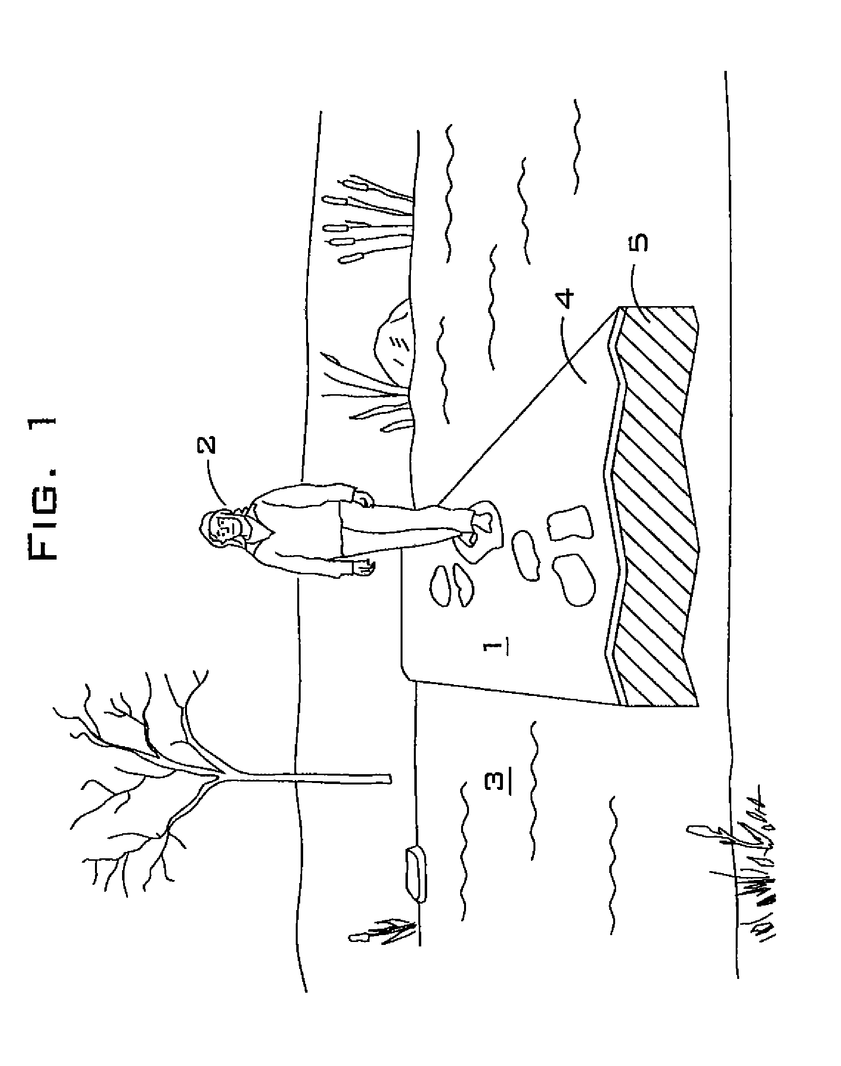
[0062]FIG. 1 illustrates a first embodiment of the invention. In this embodiment, the invention is used as a floating walkway to cross a stream. One end of the island has been removed to show the internal construction. As shown, floating walkway 1 is used by pedestrian 2 to cross water body 3. In this embodiment, rigidity for the floating walkway 1 is preferably provided by top covering 4, which is installed above interior section 5. Permeable and buoyant interior section 5 is preferably located beneath semi-rigid top covering 4. Top covering 4 is preferably impermeable to water, and impenetrable by plant stems or roots. Internal section 5 is preferably constructed so as to be buoyant, permeable to water, and penetrable by plant roots. In one embodiment, internal section 5 is comprised of nonwoven polymer matrix that is injected with buoyant polymer foam. In another embodiment, internal section 5 is comprised of bi-cellular polymer foam.

[0063]Plants (not shown) may optionally be gro...


PUM

PropertyMeasurementUnit
thickaaaaaaaaaa
thickaaaaaaaaaa
lengthsaaaaaaaaaa

Abstract

A buoyant walkway or island and its method of manufacture. In a preferred embodiment, the buoyant walkway comprising: an internal frame comprising semi-rigid members that are attached to one another, said internal semi-rigid frame having openings; an internal block disposed in each of said openings, said internal blocks being spaced apart from one another by gaps and forming a top surface and a bottom surface; cured thermoplastic foam disposed in said gaps that attach said internal blocks to said semi-rigid internal frame and to one another; a permeable top layer that is attached to said top surface; and a bottom layer that is attached to said bottom surface.

Description

CROSS-REFERENCE TO RELATED APPLICATION[0001]This application claims priority back to U.S. Patent Application No. 60 / 862,444, filed on 21 Oct. 2006.BACKGROUND OF THE INVENTION[0002]This invention relates to floating islands that are designed to provide highly buoyant, semi-rigid platforms for various applications such as walkways, roadways, docks, piers, water treatment facilities, and bird nesting habitat.[0003]Some embodiments of the present invention may be used as alternatives to footbridges and vehicular bridges. They provide access across ponds, streams and bays, and also provide access to objects such as docks and islands that are situated in water bodies. Floating walkways and roadways may be preferable to conventional pile-supported bridges because they can be less expensive to construct, faster to install, easier to move, and more adaptable to water level fluctuations. Floating walkways and roadways may also be preferable to conventional bridges at locations where the water...

Claims


Application Information

Patent Timeline
Patent Type & Authority Patents(United States)
IPC IPC(8): A01G9/02
CPCB63B35/34E02B3/064E01D15/20Y10T29/49826
Inventor KANIA, BRUCE G.STEWART, FRANK M.
Owner FOUNTAINHEAD
Learn More