
Sulfonylimide salt and method for producing the same

a technology of sulfonylsulfonylsulfonyl and sulfonylsulfonylsulfonylsulfonylsulfonylsulfonylsulfonylsulfonylsulfonylsulfonylsulfonylsulfonylsulfonylsulfonylsulfon

Active Publication Date: 2012-03-13
NIPPON SHOKUBAI CO LTD
View PDF11 Cites 24 Cited by
  • Summary
  • Abstract
  • Description
  • Claims
  • Application Information

AI Technical Summary

Benefits of technology

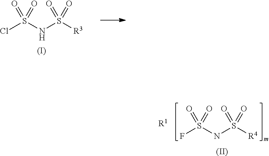
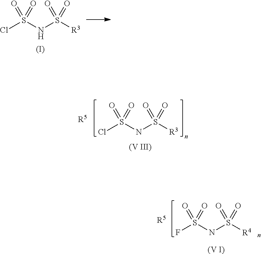
The present invention provides a method for producing fluorosulfonylimides, such as di(fluorosulfonyl)imide and salts thereof, more safely, rapidly, and efficiently. The method involves reacting a fluoride compound containing at least one element selected from the group consisting of elements of Group 11 to Group 15 and Period 4 to Period 6 (excluding arsenic and antimony) with a compound represented by the general formula (I) to obtain a fluorosulfonylimide salt. The method also includes steps of reacting the compound represented by the general formula (I) with an onium salt to give an organic salt of chlorosulfonylimide, and then reacting the organic salt with a fluoride compound containing at least one element selected from the group consisting of elements of Group 11 to Group 15 and Period 4 to Period 6 (excluding arsenic and antimony) to obtain a compound represented by the general formula (VI). The method also includes the use of specific elements, such as fluorine, chlorine, and fluorinated alkyl groups. The resulting fluorosulfonylimides have applications in various fields and are safer, faster, and more efficient to produce.

Problems solved by technology

However, when AsF3 is used as the fluorinating agent, there are problems that it is difficult to avoid the generation of by-products, which are not easily separated from the product, and that AsF3 is comparatively expensive.
Since hydrogen fluoride is a substance having strong toxicity and corrosiveness, when the product contains hydrogen fluoride, not only a reaction apparatus but also peripheral members may be corroded when the di(fluorosulfonyl)imide is used as a salt in various applications.
Furthermore, the method described in Patent Document 1 has a problem that the reaction requires a long time.

Method used


Image

  • Sulfonylimide salt and method for producing the same
  • Sulfonylimide salt and method for producing the same
  • Sulfonylimide salt and method for producing the same

Examples


synthesis example 1

Synthesis of Chlorosulfonyl Isocyanate

[0090]In a 200 ml reaction vessel equipped with a stirrer, a thermometer, a reflux apparatus and a gas introducing tube, 80.1 g (1.0 mol) of liquid sulfuric anhydride (SO3) was charged and 61.5 g (0.53 mol) of a cyanogen chloride gas (CNCl) was introduced at a temperature of 25° C. to 35° C. over 2 hours, and the temperature of the reaction solution was adjusted to 25° C. to 30° C., followed by stirring for 0.5 hour. After completion of the reaction, the reflux apparatus and the gas introducing tube were removed from the reaction vessel, followed by distillation under a normal pressure to obtain a colorless transparent liquid: 83.7%) as a fraction at 106° C. to 107° C. (yield (amount): 118.5 g, 0.83 mol, yield (percentage).

synthesis example 2

Synthesis of Di(chlorosulfonyl)imide

[0091]In a 500 ml reaction vessel equipped with a stirrer, a thermometer, a reflux apparatus and a dropping device, 148.7 g (1.28 mol) of chlorosulfonic acid (ClSO3H) was added, followed by heating to 120° C. Then, 180.4 g (1.27 mol) of chlorosulfonyl isocyanate obtained in the same manner as in Synthesis Example 1 was added to the reaction vessel from the dropping device over 2 hours and the mixed solution was heated to 150° C., followed by stirring for 6 hours. After completion of the reaction, the reflux tube and the dropping device were removed from the reaction vessel, followed by distillation under reduced pressure to obtain a colorless transparent liquid as a fraction at 104° C. to 106° C. (0.3 kPa) (yield (amount): 178.4 g, 0.83 mol, yield (percentage): 65.6%).

[0092]Compound identification was carried out by IR (Varian 2000 FT-IR, manufactured by Varian, Inc., liquid membrane technique) and it was confirmed that the resulting colorless tra...

synthesis example 3

Synthesis of Bis[di(fluorosulfonyl)imide]zinc salt

[0093]In a 20 ml reaction vessel, 2.18 g (0.01 mol) of di(chlorosulfonyl)imide and 4.36 g of acetonitrile were added, followed by stirring. Into the reaction vessel, 2.63 g (0.025 mol) of ZnF2 (Zinc fluoride) was added, followed by conducting a reaction at room temperature (25° C.) for 24 hours. The reaction solution was filtrated and the filtered material was washed with 5 g of acetonitrile, and then the solution prepared by combining the filtrate with the wash liquid was analyzed by 19F-NMR (“Unity plus, Model 400”, manufactured by Varian, Inc., internal standard substance: trifluoromethylbenzene, integration time: 32). A peak area of the resulting chart was measured and the rate of conversion from chlorine into fluorine was determined and thus it was confirmed that the reaction quantitatively proceeded and a bis[di(fluorosulfonyl)imide]zinc salt was obtained.

[0094]19F-NMR (CD3CN): δ56.0


PUM

PropertyMeasurementUnit
temperatureaaaaaaaaaa
reaction timeaaaaaaaaaa

Abstract

The present invention provides a method for producing fluorosulfonylimides more safely, rapidly and efficiently, which enables suppression of production of by-products, and fluorosulfonylimides. The method for producing a fluorosulfonylimide salt of the present invention includes a step of reacting a fluoride compound containing at least one element selected from the group consisting of elements of Group 11 to Group 15 and Period 4 to Period 6 (excluding arsenic and antimony) with a compound represented by the following general formula (I) to give a fluorosulfonylimide salt represented by the general formula (II):[Chemical Formula 1]wherein R1 denotes at least one element selected from the group consisting of elements of Group 11 to Group 15 and Period 4 to Period 6 (excluding arsenic and antimony); R3 denotes fluorine, chlorine or a fluorinated alkyl group having 1 to 6 carbon atoms; R4 denotes fluorine or a fluorinated alkyl group having 1 to 6 carbon atoms; and m denotes an integer of 2 or 3.

Description

TECHNICAL FIELD[0001]The present invention relates to fluorosulfonylimides, and more particularly to N-(fluorosulfonyl)-N-(fluoroalkylsulfonyl)imide, di(fluorosulfonyl)imide and a derivative thereof such as a salt thereof, and a method for producing the same.BACKGROUND ART[0002]Fluorosulfonylimides such as N-(fluorosulfonyl)-N-(fluoroalkylsulfonyl)imide and di(fluorosulfonyl)imide, and derivatives thereof are useful as intermediates for compounds having a N(SO2F) group or an N(SO2F)2 group, and are also useful compounds in various applications, for example, electrolytes, additives for electrolytic solutions of fuel cells, selective electrophilic fluorinating agents, photo acid generators, thermal acid generators, and near infrared light-absorbing dyes.[0003]Di(fluorosulfonyl)imides described above have conventionally been prepared by a halogen exchange reaction of di(chlorosulfonyl)imide using a fluorinating agent. For example, arsenic trifluoride (AsF3) is used as a fluorinating ag...

Claims


Application Information

Patent Timeline
Patent Type & Authority Patents(United States)
IPC IPC(8): C07C303/00
CPCC07C303/40C07C311/48
Inventor OKUMURA, YASUNORITAKEI, KAZUOSATO, SHIMPEISATO, YUICHI
Owner NIPPON SHOKUBAI CO LTD
Learn More