Method of producing alloyed iron article
a technology of alloyed iron and alloyed iron, which is applied in the direction of chemical vapor deposition coating, plant products, plasma techniques, etc., can solve the problem that the industry is currently limited to providing coatings
- Summary
- Abstract
- Description
- Claims
- Application Information
AI Technical Summary
Benefits of technology
Problems solved by technology
Method used
Image
Examples
example 1
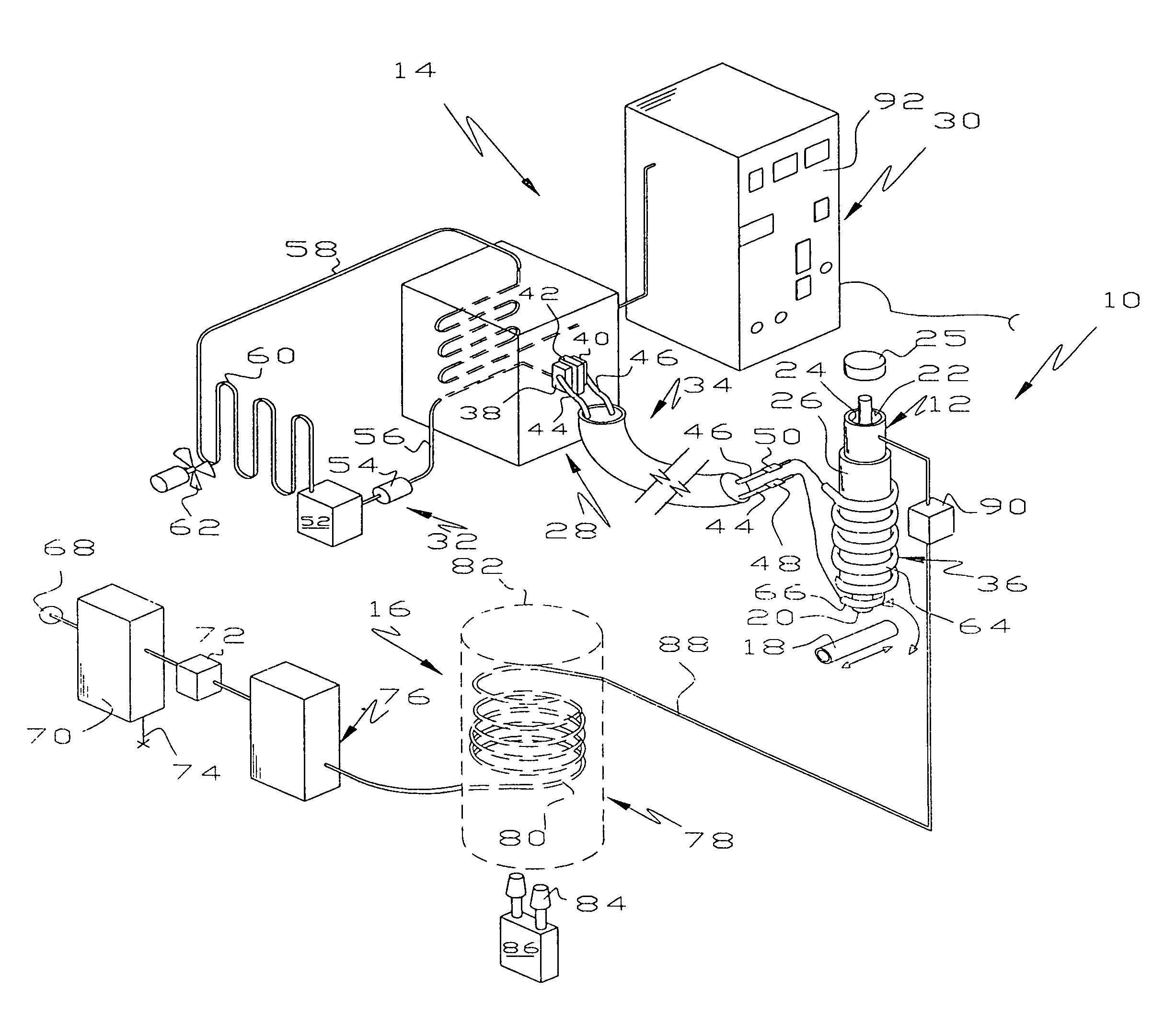
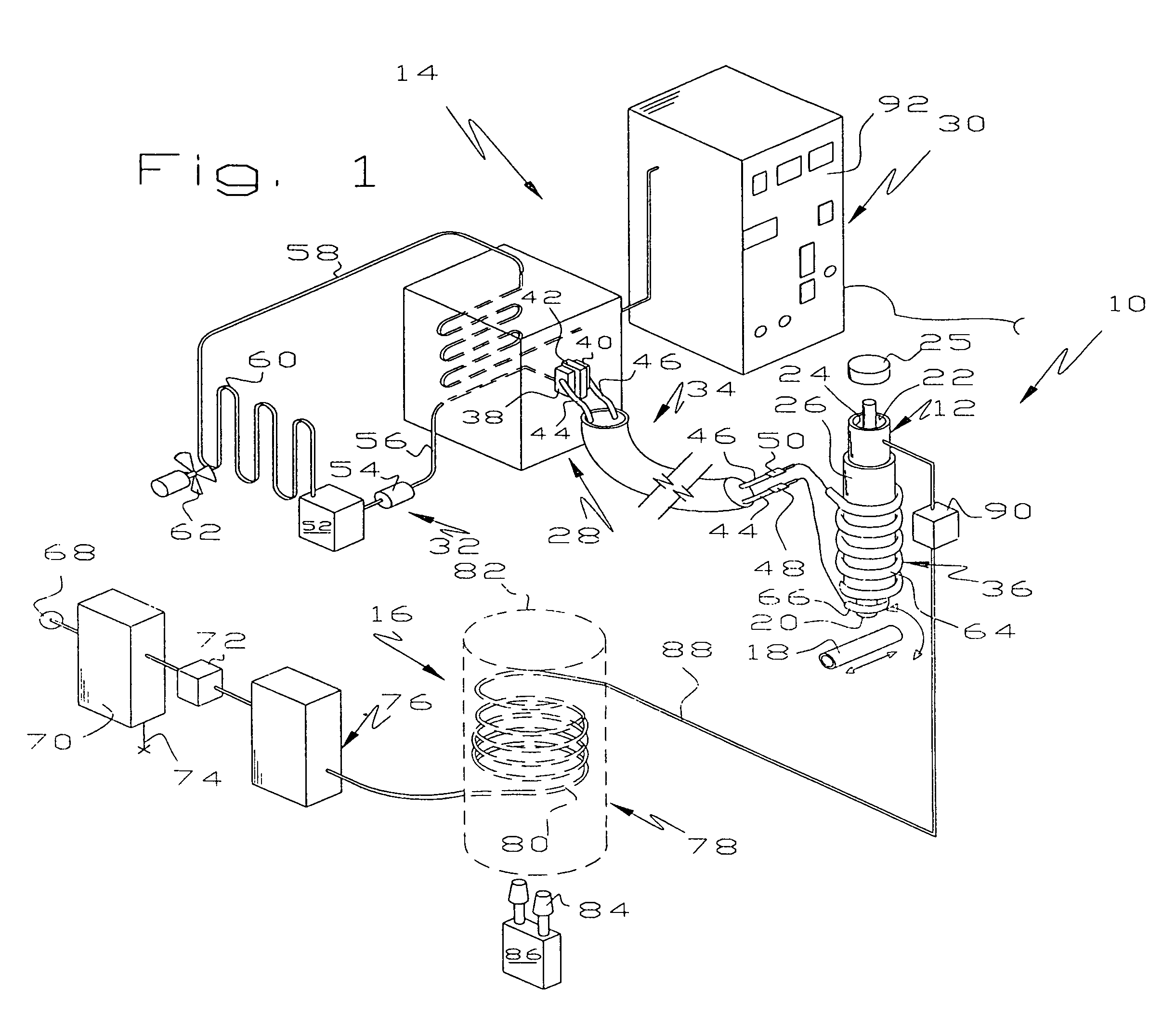
[0048]A flat specimen was made of carbon steel 4140 was analyzed for coating chemistry and thickness of the coating at five points. The specimen was coated by manually moving the article under the nozzle of the container 12 as shown in FIG. 1. This sample was analyzed using an Amray scanning electron microscope equipped with a Kevex energy dispersive X-ray spectrometer. The coating was analyzed by Constellation Technology Laboratories as follows:
[0049]
Semi-quantitative Chemistry by Weight PercentO1.3%Al93.4%Si.8%Fe4.1%Na.3%
Thickness of the coating was measured at five locations. The results were, in microns: 14.9, 17.1, 16.8, 15.1 and 17.5 and averaged 16.3 microns. The coating is surprisingly uniform given the fact that the substrate was manually moved back and forth under the spray nozzle.
example 2
[0050]Another flat specimen made of carbon steel 4140 was received for SEM / EDS analysis for coating chemistry, and thickness of the coating at five points. The sample was coated by manually moving the article under the nozzle of the container 12 as shown in FIG. 1. The sample was analyzed using an Amray scanning electron microscope (SEM) equipped with a Kevex energy dispersive X-ray spectrometer (EDS). The results were:
[0051]
C18.7%O2.1%Al70.1%Si5.2%Fe1.7%Cu2.3%
The coating adhesion test coupon was prepared by adhering two round couplings to the coating and substrate using 3M SCOTCHWELD 2214. The specimen was then tested for adhesions using a Tinius Olsen LoCap tensile tester with the 30,000 pound load cell. The coating separated from the substrate on a 1.00 inch diameter specimen at 3473 pounds showing an ultimate tensile strength of 4422 psi.
example 3
[0052]A flat steel specimen of carbon steel 4140 was coated by manually moving the article under the nozzle of a container as shown in FIG. 1. The sample was adhesion tested per ASTM B-633. The sample was prepared by adhering 1″ diameter steel bars to the coating using 3M adhesive 2214. A blank specimen was prepared using the same technique to validate the strength of the adhesive. The testing was performed using a Tinius Olsen LoCap tensile tester using the 30,000-pound load cell. The tensile load applied to the specimen at failure was 6874 pounds and the tensile strength of the coating was 8757 psi. At failure of the adhesive on the uncoated specimen, 8597 pounds was applied showing a tensile strength of the adhesive to be 10952 psi.
PUM
| Property | Measurement | Unit |
|---|---|---|
| frequency | aaaaa | aaaaa |
| frequency | aaaaa | aaaaa |
| voltage | aaaaa | aaaaa |
Abstract
Description
Claims
Application Information
 - R&D
- Intellectual Property
- Life Sciences
- Materials
- Tech Scout
- Unparalleled Data Quality
- Higher Quality Content
- 60% Fewer Hallucinations
Browse by: Latest US Patents, China's latest patents, Technical Efficacy Thesaurus, Application Domain, Technology Topic, Popular Technical Reports.
© 2025 PatSnap. All rights reserved.Legal|Privacy policy|Modern Slavery Act Transparency Statement|Sitemap|About US| Contact US: help@patsnap.com


