Method and apparatus for producing iron article and product

a technology of iron articles and products, applied in the direction of special dispensing means, molten metal supply equipments, rigid containers, etc., can solve the problems of poor pressure, and achieve the effect of preventing rust or corrosion of the underlying iron alloy

Inactive Publication Date: 2005-07-05
UPCHURCH CHARLES J
View PDF9 Cites 4 Cited by
  • Summary
  • Abstract
  • Description
  • Claims
  • Application Information

AI Technical Summary

Benefits of technology

[0006]In this invention, aluminum is applied to iron alloys in such a way to provide an aluminum layer that substantially prevents rust or corrosion of the underly

Problems solved by technology

Higher pressures do not appear to provid

Method used


Image

  • Method and apparatus for producing iron article and product
  • Method and apparatus for producing iron article and product
  • Method and apparatus for producing iron article and product

Examples


example 1

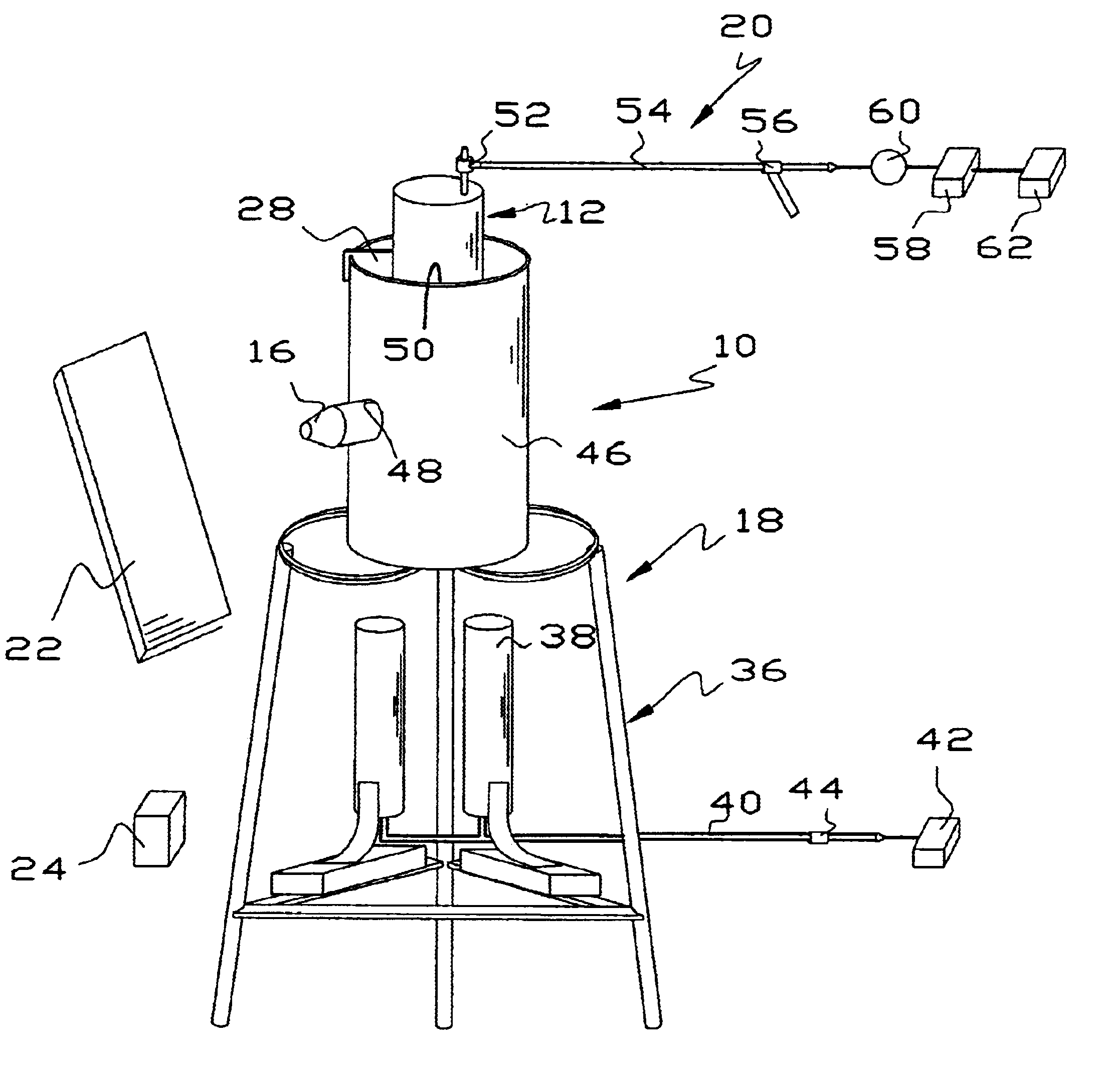
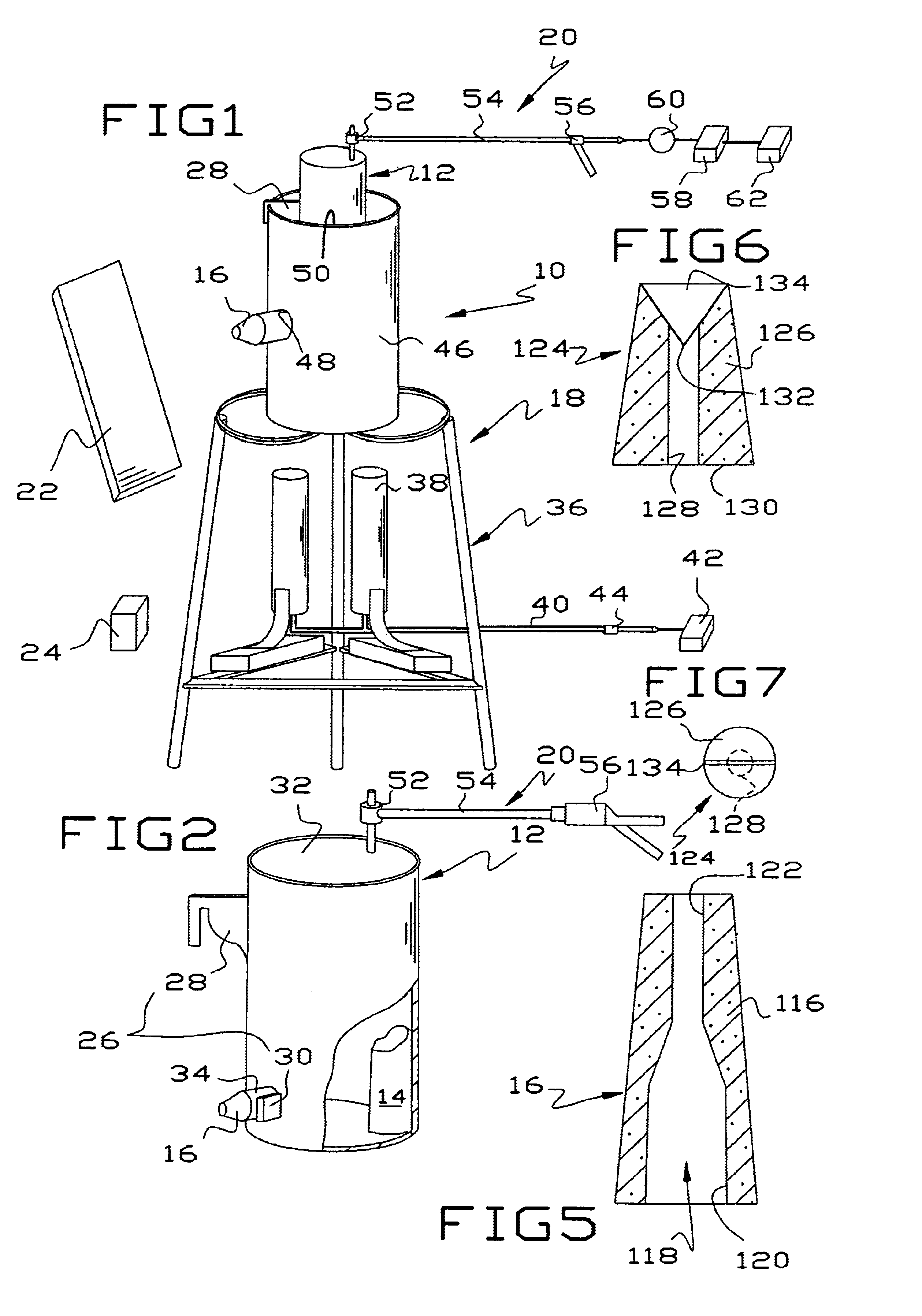
[0046]A 1″ wide×0.1″ thick mild carbon steel strap 8½″ long was wire brushed to remove loose rust and grasped with long handled tongs. The steel strap was heated in the flame of an acetylene torch until it was cherry red. A thermocouple type thermometer revealed the temperature to be 1100° F. Aluminum was heated in a steel container by propane torches in a prototype device substantially identical to FIGS. 1-2, using a nozzle substantially as shown in FIG. 5, until the aluminum began to melt by the formation of aluminum droplets on the surface of the aluminum. Compressed air at 120 psig was delivered by a commercial air compressor into the top of the container propelling a fine aluminum mist out of the ceramic nozzle. The heated steel strap was passed in front of the nozzle and an aluminum layer was deposited on the steel strap. Several aluminum layers were deposited on the steel strap, one after another simply by moving the strap back and forth in front of the nozzle. The steel stra...

example 2

[0047]A ¼″×4″ flat bar was cleaned with a wire brush and heated to cherry red and sprayed with an aluminum mist as in Example 1. After the bar cooled somewhat, but well above ambient, the bar was placed in a vise and was bent 90° into a right angle by using a torch to heat it. The reheated bar was struck with a hammer and bent on the vise. Inspection of the bend showed no cracks or pin holes in the aluminum layer. The aluminized layer could not be buffed off with a wire wheel mounted on a 4″ grinder driven by an electric motor.

example 3

[0048]A ½″×12″×12″ steel plate was heated to cherry red and sprayed with aluminum mist as in Example 1. After the plate cooled, welds were applied to the exterior with a conventional electric arc welding rig. Upon visual inspection, the aluminized layer had not burned away from or retreated from the edge of the weld. A month later, there was no rust on the steel plate except at the locations where tongs were used to hold the plate when heated and sprayed.


PUM

PropertyMeasurementUnit
Temperatureaaaaaaaaaa

Abstract

Liquid aluminum is sprayed onto an iron article to produce a thin tenacious non-corrodible layer. In one embodiment, an iron article is heated to at least 400° F. or preferably until cherry red. It is sprayed with a fine aluminum mist generated by heating aluminum in a container and then passing a gas under pressure through the container and out through a heat resistant ceramic nozzle. In another embodiment, aluminum is heated to at least 2000° F. in a container to produce a pool of liquid aluminum. Pressure is applied to the container to project the liquid aluminum in the form of a fine mist through a ceramic nozzle onto the iron article. The aluminum mist produces a tenacious aluminum layer on the iron article that is workable, weldable and non-corrodible. The aluminum layer is a permanent part of the iron article and cannot be removed by conventional means, such as buffing with a wire wheel driven by a electric motor.

Description

[0001]This application is based on provisional application Ser. No. 60 / 404,243, filed Aug. 19, 2002, entitled METHOD OF APPLYING AN ALUMINUM LAYER TO IRON ALLOYS AND RESULTANT ARTICLE.[0002]This invention is a method and apparatus for producing non-corrodible iron articles and the product produced thereby.BACKGROUND OF THE INVENTION[0003]It is well known that iron articles, which is used herein to include articles made of steel or other iron alloys, corrode easily by the reaction of iron with oxygen to produce ferrous oxide. The exception, of course, are a group of nickel rich iron alloys sometimes referred to as stainless steels. There has accordingly developed a large industry aimed at prevention or control of iron deterioration due to oxidation.[0004]In a broad sense, the industry is currently limited to providing coatings which prevent oxygen from reaching the iron article although there other proposals have been made in the literature or have been attempted in the past. For exa...

Claims


Application Information

Patent Timeline
IPC IPC(8): C23C4/12
CPCC23C4/121Y10S428/937Y10S428/926Y10T428/12764Y10T428/12757Y10T428/12986Y10T428/12993C23C4/123
Inventor UPCHURCH, CHARLES J.
Owner UPCHURCH CHARLES J
Why Eureka
Try Eureka