Advanced renewable energy harvesting

a technology of renewable energy and power management, applied in the direction of electric variable regulation, process and machine control, instruments, etc., can solve the problems of limiting the overall or maximum system power, and affecting the efficiency of the overall system power, so as to maximize the power of each panel, minimize transmission wire losses, and efficiently invert the dc to ac voltage

Inactive Publication Date: 2012-03-20
EIQ ENERGY INC
View PDF9 Cites 167 Cited by
  • Summary
  • Abstract
  • Description
  • Claims
  • Application Information

AI Technical Summary

Benefits of technology

[0016]In one embodiment, the invention provides a separate DC DC boost converter and maximum power point tracking (MPPT) component for each energy gathering source. In one embodiment, the energy gathering source is a solar panel. The MPPT component matches the output impedance of the panels to the input impedance of the boost converter to maximize the power for each panel. The individual converter component boosts output voltage of the panels to a voltage that is high enough to minimize transmission wire losses while efficiently inverting the DC to an AC voltage.
[0017]Using a parallel method of interconnecting a number of solar panels with a constant voltage output to a DC buss eliminates the problems associated with using a string of series-connected solar panels. This system allows the current from each individually optimized panel to sum together to produce a current that is independent of the efficiency or solar conversion capability of any one panel. As a result, the system overcomes the Christmas light problem because the system continues to function even with broken panels.
[0018]This creates the freedom to use different solar panels with different IV characteristics, panels constructed from different PV technologies, and panels installed at different orientations relative to the sun. In one embodiment, additional panels are added to the installation at any time. In another embodiment, other power sources, e.g. fuel cells, batteries, wind turbines, etc. are coupled to individual converter components and attached to the DC buss for either point of use or DC to AC conversion for use or sale back to the utility company.
[0019]In another embodiment, a communications component is coupled to each panel for monitoring. The monitoring system provides information such as panel ID, temperature, voltage, current, power, efficiency, diagnostics, etc. The monitoring system is for individual users or a company that harvests the energy. This information helps technicians immediately identify malfunctioning panels and maximizes the efficiency of each panel. The monitoring system also provides information regarding the output and efficiency of the complete system and alerts the producer of underperformance or problematic power production.

Problems solved by technology

Panels connected in series can lose up to 60% of their energy as a result of being limited by the worst-performing panel.
Because of these variations, a traditional DC-to-AC inverter used in a series-connection system is subjected to high stress and heat levels resulting in a one percent failure rate within the first six months.
This approach suffers from a limitation on overall or maximum system power that may be harvested at any point in time due to the series connection of panels, and the requirement that the current flowing through such a series circuit cannot be any greater than that produced by the panel with the smallest output current.
The design of series-connected panel systems is time consuming.
The maintenance of series-connected panel systems is also time-consuming.
When a system is connected in series, any defects in one of the panels will cause the entire system to fail.
This is the same defect that occurs in a string of Christmas lights when one of the lights breaks.
As a result, the cost of hiring a technician to visit the site and locate the defective panel is prohibitively expensive.

Method used


Image

  • Advanced renewable energy harvesting
  • Advanced renewable energy harvesting
  • Advanced renewable energy harvesting

Examples


Embodiment Construction

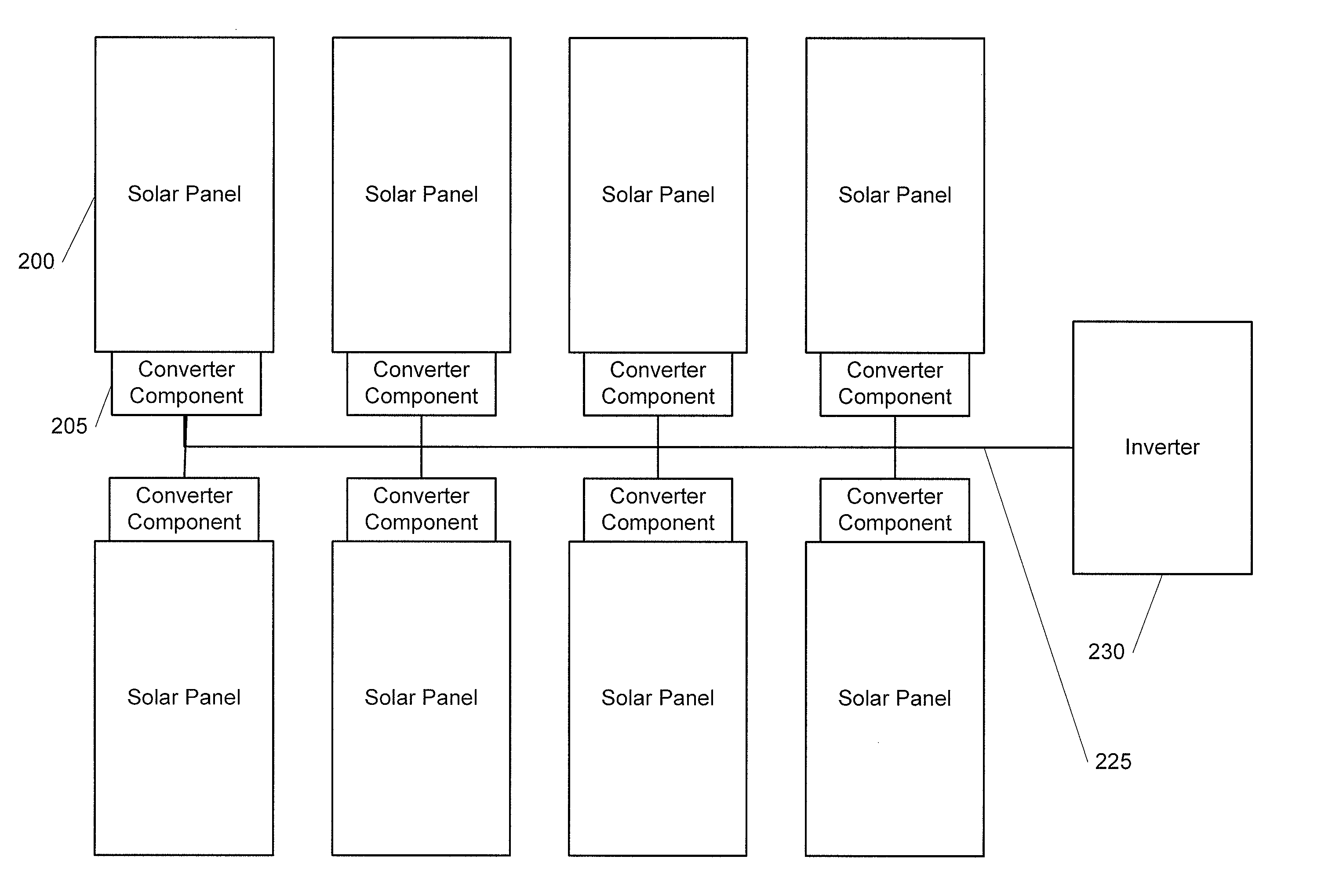
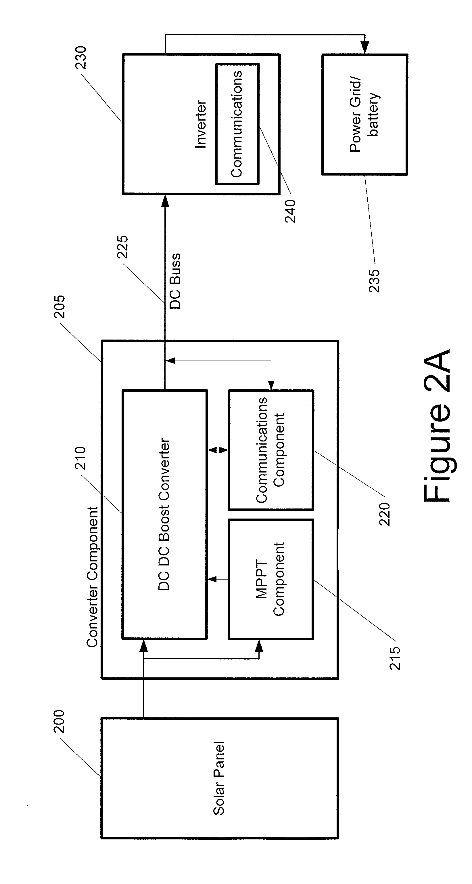
[0026]The invention is a system and method for harvesting electrical energy from solar panels and for converting it into energy. Each solar panel is coupled to a converter component, which is connected in parallel to a DC power buss. The converter component includes a DC DC boost converter for boosting the panel's output voltage for DC transmission on a power buss, an MPPT component for maximizing energy transfer between the panel and the transmission buss, and a communication component for receiving information about the panel and transmitting the information to a user and a company that manages the panels. The power buss is connected to an inverter for changing the power from a direct current (DC) to an alternating current (AC) and generating an AC that is in phase with the power grid.

[0027]One embodiment of the system for each solar panel is illustrated in FIG. 2A. In one embodiment, the power is obtained from solar panels 200. In another embodiment, the power is obtained from an...


PUM


Abstract

The power of DC electrical sources is combined onto a DC buss, such that each source behaves independently from any other source attached to the buss. In one embodiment, a converter module is attached to each of a plurality of solar photovoltaic panels and its output is attached in a parallel manner to a common buss that forms the input to a DC AC inverter. The converter module includes a Maximum Power Point Tracking component that matches the output impedance of the panels to the input impedance of the converter module. The converter also includes a communication component that provides parametric data and identification to a central inverter. Data generated by each converter module is transmitted over the power line or by wireless means and is collected at the inverter and forwarded to a data collection and reporting system.

Description

CROSS REFERENCE TO RELATED APPLICATIONS[0001]This patent application claims the benefit of U.S. provisional patent application Ser. No. 61 / 016,365, Packaging, Assembly, and Mounting of Photovoltaic Solar Panels, filed Dec. 21, 2007, the entirety of which is incorporated herein by this reference thereto.BACKGROUND OF THE INVENTION[0002]1. Technical Field[0003]This invention relates generally to the field of renewable energy power management. More specifically, this invention relates to the power production, power conversion, and power management of DC energy sources systems.[0004]2. Description of the Related Art[0005]Coal-burning energy produces some of the highest greenhouse-gas emissions of any of the fuels in widespread use. The United States currently uses coal-burning fuel to provide about half of the country's electric power. The United States is continually striving to find cheap and efficient ways to generate its own clean energy in an effort to improve the environment and a...

Claims


Application Information

Patent Timeline
Patent Type & Authority Patents(United States)
IPC IPC(8): H02J1/00H02J3/00
CPCH02J1/10H02J7/35H02J13/0075Y02E40/72Y02E10/58Y04S10/123Y02E10/566G05F1/67H02J2300/26H02J3/381Y02E10/56Y02E40/70Y04S40/126Y02E60/00H02J13/00022H02J3/40
Inventor ALLEN, JAMESKRZYWINSKI, EUGENESPEERS, TROY
Owner EIQ ENERGY INC
Why Eureka
Try Eureka