Physical properties detection device and physical properties detection method

a detection device and physical property technology, applied in the field of physical properties detection devices and physical properties detection methods, can solve the problems of difficult reading of recorded information and difficult measurement of polarization

Inactive Publication Date: 2012-03-20
PIONEER CORP
View PDF11 Cites 0 Cited by
  • Summary
  • Abstract
  • Description
  • Claims
  • Application Information

AI Technical Summary

Problems solved by technology

However, the polarization in a ferroelectric material is masked by electrons, ions, and other surface charges adhering to the surface of the material, the polarization has been difficult to measure; i.e., recorded information has been difficult to read.

Method used


Image

  • Physical properties detection device and physical properties detection method
  • Physical properties detection device and physical properties detection method
  • Physical properties detection device and physical properties detection method

Examples


first embodiment

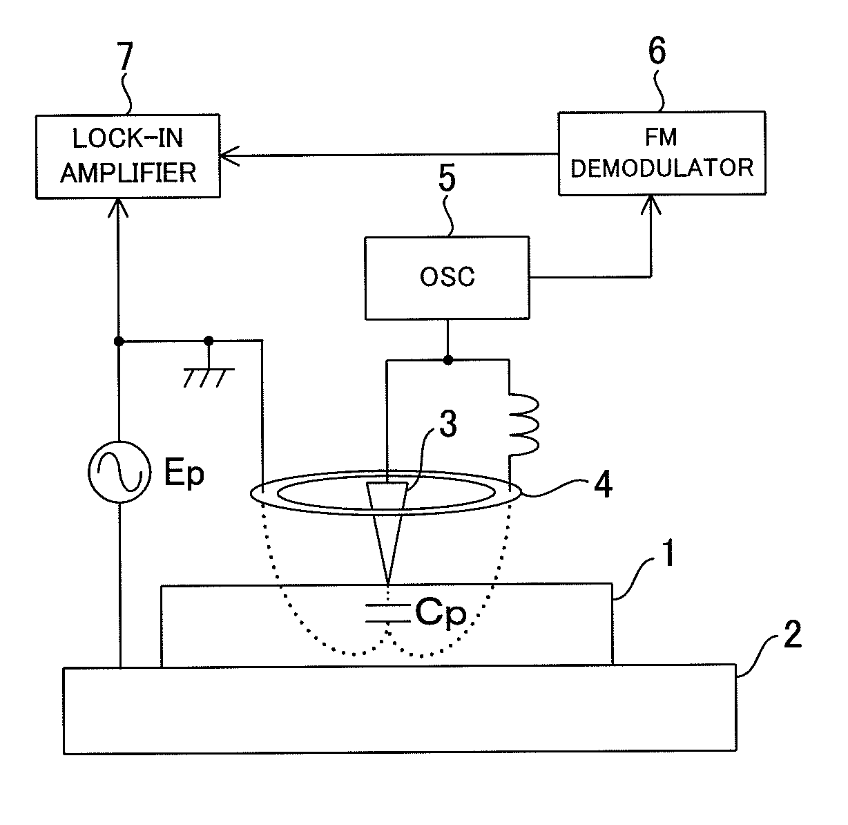
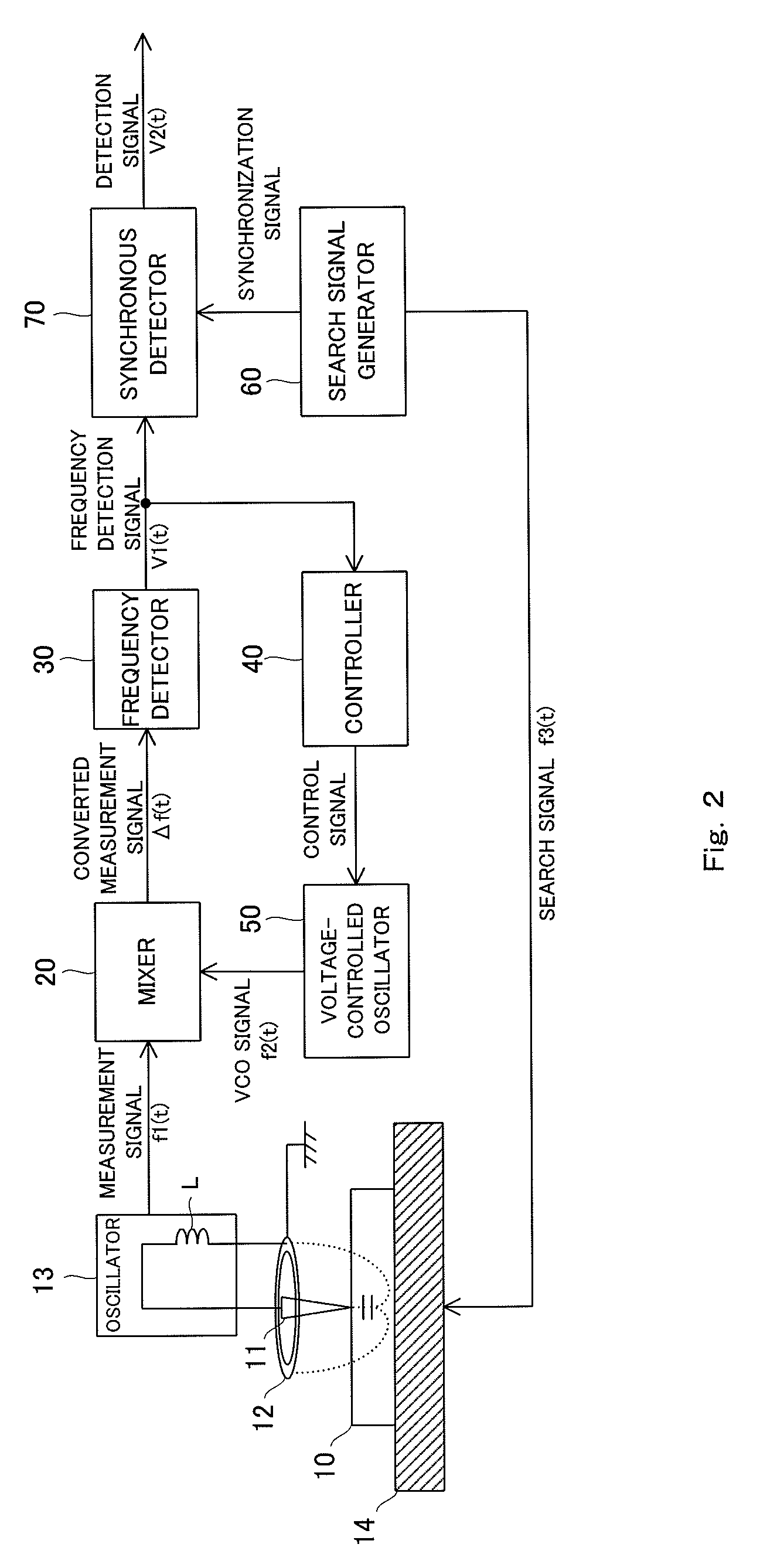
[0037]FIG. 2 is a block diagram showing the physical properties detection device as an embodiment of the present invention. The overall structure of the physical properties detection device will be described with reference to FIG. 2.

[0038]While a search signal generator 60 generates a search signal f3(t), applies the search signal f3(t) to a recording medium 10 via a metal stage 14, the search signal generator 60 generates a synchronization signal, and feeds the synchronization signal to a synchronous detector 70. The recording medium 10 is the measurement subject of the physical properties detection device of the present invention, and is formed from a ferroelectric material. A probe 11 is positioned so that the distal end thereof is near or touching the recording medium 10, and a variation of the capacitance Cp directly below the probe 11 that accompanies application of the search signal f3(t) is read by the probe 11 and a ring probe 12, and data recorded in the recording medium 1...

second embodiment

[0070]A second embodiment of the physical properties detection device of the present invention will next be described. The configuration of the controller 40 shown in FIG. 5 in the first embodiment described above can be applied when the relation f1>f2 is always true regarding the relationship between the frequency f1 of the measurement signal f1(t) and the frequency f2 of the VCO signal f2(t). In contrast, the configuration of the second embodiment can be applied when the relation f12 is always true.

[0071]FIG. 11 is a block diagram showing the specific structure of the controller 40′ of the second embodiment. The controller 40′ is composed of a subtractor 41, a lock detector 43, and a non-inverting integrator 44. The subtractor 41 subtracts a frequency detection signal from a target frequency signal fr and outputs the result as an error signal. The non-inverting integrator 44 integrates the error signal and outputs a control signal without inverting the phase of the error signal, s...

third embodiment

[0077]A third embodiment of the physical properties detection device of the present invention will next be described. FIG. 13 is a block diagram showing the structure of the physical properties detection device according to the third embodiment of the present invention. The device of the third embodiment is a recording / reproduction device that comprises a recording pulse generator 80 and a changeover switch 90 in addition to the structure of the first embodiment shown in FIG. 2. The recording pulse generator 80 generates a recording pulse that corresponds to data to be recorded in the recording medium 10. The recording pulse may be a sine wave or a rectangular wave, but must have a voltage level sufficient to enable data to be written to the recording medium 10. The changeover switch 90 is connected to the recording pulse generator 80 during recording of data in the recording medium 10, and the changeover switch 90 is connected to the search signal generator 60 during reproducing of...


PUM

PropertyMeasurementUnit
capacitanceaaaaaaaaaa
oscillation frequencyaaaaaaaaaa
frequencyaaaaaaaaaa

Abstract

A physical properties detection device comprising a probe to be placed near or touching a surface of a ferroelectric; an oscillation loop including the probe and capacitance within the ferroelectric; and detection means for detecting a physical properties of the ferroelectric on the basis of a frequency variation of a measurement signal generated in the oscillation loop, the frequency variation accompanying application of an alternating electric field to the ferroelectric; and the physical properties detection device is further comprising frequency conversion means for converting the frequency of the measurement signal to a low frequency and outputting the resulting signal as a converted measurement signal; frequency control means for controlling the frequency of the converted measurement signal so as to match a target frequency; frequency detection means for generating a frequency detection signal that has a signal level corresponding to the frequency of the converted measurement signal; and synchronous detection means for synchronously detecting the frequency detection signal on the basis of a synchronization signal.

Description

TECHNICAL FIELD[0001]The present invention relates to a physical properties detection device and physical properties detection method for detecting a physical properties that accompanies a capacitance variation, such as the polarization direction of a ferroelectric material.BACKGROUND ART[0002]Recent increases in information volume have led to an increased need for techniques for storing information at high speed and capacity. The recording density of magnetic storage, the most widely used form of information recording, is currently approaching the theoretical limit, and a recording density of 1 Tbit / inch2 is considered to be the limit even when perpendicular magnetic recording is used. On the other hand, ferroelectrics have spontaneous polarization, and the polarization direction thereof can be reversed by applying an electric field from the outside. Consequently, digital data can be correlated to the orientation of this polarization in order to record information. It is widely kno...

Claims


Application Information

Patent Timeline
Patent Type & Authority Patents(United States)
IPC IPC(8): G01N27/00
CPCG11B9/02G11B9/06
Inventor TATEISHI, KIYOSHIMAEDA, TAKANORIKOBAYASHI, HIDEKIYABE, TOMOTAKA
Owner PIONEER CORP
Why Eureka
Try Eureka