Method and structure for magnetically-directed, self-assembly of three-dimensional structures

a three-dimensional structure and self-assembly technology, applied in the direction of magnetic bodies, final product manufacturing, sustainable manufacturing/processing, etc., can solve the problems of over-powering the throughput capability of serial back-end packaging and assembly, and the advancement of electronic and photonic devices for signal processing, wireless communication, computing and the lik

Active Publication Date: 2012-03-20
UNIV OF FLORIDA RES FOUNDATION INC
View PDF20 Cites 47 Cited by
  • Summary
  • Abstract
  • Description
  • Claims
  • Application Information

AI Technical Summary

Benefits of technology

[0027]The magnet or magnets of the second body may either be magnetically hard, having a magnetic polarity opposite to the polarity of the first magnet or magnets, or may be magnetically soft in which it becomes magnetized in the presence of the magnetic field from the first pattern. A magnetically hard magnet, or permanent magnet, has a permanent magnetic polarization. A magnetically soft magnet, or soft magnet, becomes magnetized, and exhibits a magnetic field, in the presence of another magnetic field. The size and arrangement of the first pattern and second pattern being sufficient so that when the first pattern is in close proximity to the second pattern, and substantially aligned, the attraction force between the first magnetic field pattern and the second magnetic field pattern is sufficient to overcome a mixing force. The magnetic attraction force resulting from the interaction of the first magnetic field and the second magnetic field aligns the two bodies and bonds the two bodies. Full alignment of the two bodies with respect to each other results in an energy minimum, resulting in a stable physical orientation.
[0029]During use, a first body is formed with a single magnet or plurality of magnets disposed to produce a first magnetic field having a first predetermined pattern. A second body is formed with a single magnet or plurality of magnets to produce a second pattern complimentary to the first pattern. The first body and second body are mixed together. The first body being attracted to the second body when in sufficient proximity for an attraction between the first shaped magnetic field pattern to the second shaped magnetic field pattern to overcome a mixing force. The attraction between the first shaped magnetic field pattern and second shaped magnetic field pattern overcomes the mixing force when the first pattern substantially aligns with the second pattern. The full alignment of the first body and the second body results in an energy minimization and a stable bonding arrangement.

Problems solved by technology

Over the past few decades, advances in the field of electronic and photonic devices for signal processing wireless communication, computing and the like have become more complex as they become more highly integrated.
This method has been satisfactory; however, it suffers from the disadvantage that the large number of components that can be batch manufactured overwhelm the throughput capabilities for the serial back-end packaging and assembly.
Because of the serial nature, the throughput is limited by the number and speed of the robotic manipulators.
Secondly, the shrinking physical size of the microelectronics, down to the micro- or nanoscale in many applications, requires precise manipulation.
Lastly, for sub-millimeter parts, the adhesion forces between the part and the manipulator are significant compared to gravity, resulting in a sticking problem.
This adds complexity to the structure of a substrate, is often substrate-limited, i.e., is too difficult to use between two free-floating bodies, and requires the input of energy.
However, in the prior art, the magnetic forces were the result of the entire structure being a magnet where the structures were attracted to each other, but there is no control over selectivity, or interaction.
Furthermore, the magnetic approach was also limited to substrate bonding, not to free floating bodies.
These techniques and methods for manufacture have been satisfactory; however, they do not match the full functionality offered by robotic or human part manipulation such as orientational uniqueness, bonding selectivity, or inter-part bonding.
As a result, they limit the basic logical design rules available for a designer in the self-assembly process.
In other words, certain incorrect orientations may result in a local minimization of energy, and the mixing energy is insufficient to move the part into the desired orientation to achieve the global energy minimum.
However, these approaches require parts with large scale asymmetrical physical geometries, adding cost and complexity to the batch manufacture process.
In the capillary driven self-assembly method, asymmetric bonding interfaces have been implemented, but the alignment precision decreased and the process yields dropped by nearly 70%.
The drop in yield is attributed to local energy minima creating misfits and the reduced precision was attributed to a less sharp dip in the energy curve.
Although allowing bonding selectivity, it requires substantial processing and precludes parallel assembly of heterogeneous mixtures.
Furthermore, this sequential process lengthens the assembly process as a function of the number of different components.
However, the number of mutually exclusive shapes may be limited and chip real estate may be wasted as a result of the need for size differentiation as one shape differentiator.
Furthermore, the machining of arbitrarily shaped parts imposes additional processing complexity and cost.
Therefore, the prior art provides no real solution for the bonding selectivity issue and the requirement in more complex applications for sequential selective bonding in a parallel process.
Because of this, gravity-driven processes are inapplicable because gravity only acts in one direction.
A secondary challenge for inter-part bonding is preventing agglomeration, where parts of a similar type inadvertently bond to each other rather than to the specified receptor site.
As a result, capillary-driven assembly is inapplicable because agglomeration requires that there are no short range bonding forces between similar parts, while insuring there are bonding forces between dissimilar parts.
This process has been shown to have potential to be satisfactory, however, it suffers from the drawback that it requires sequential assembly steps and the limitation of a single electrical contact between the individual parts and the requirement for parts of dissimilar size to prevent agglomeration.

Method used


Image

  • Method and structure for magnetically-directed, self-assembly of three-dimensional structures
  • Method and structure for magnetically-directed, self-assembly of three-dimensional structures
  • Method and structure for magnetically-directed, self-assembly of three-dimensional structures

Examples


Embodiment Construction

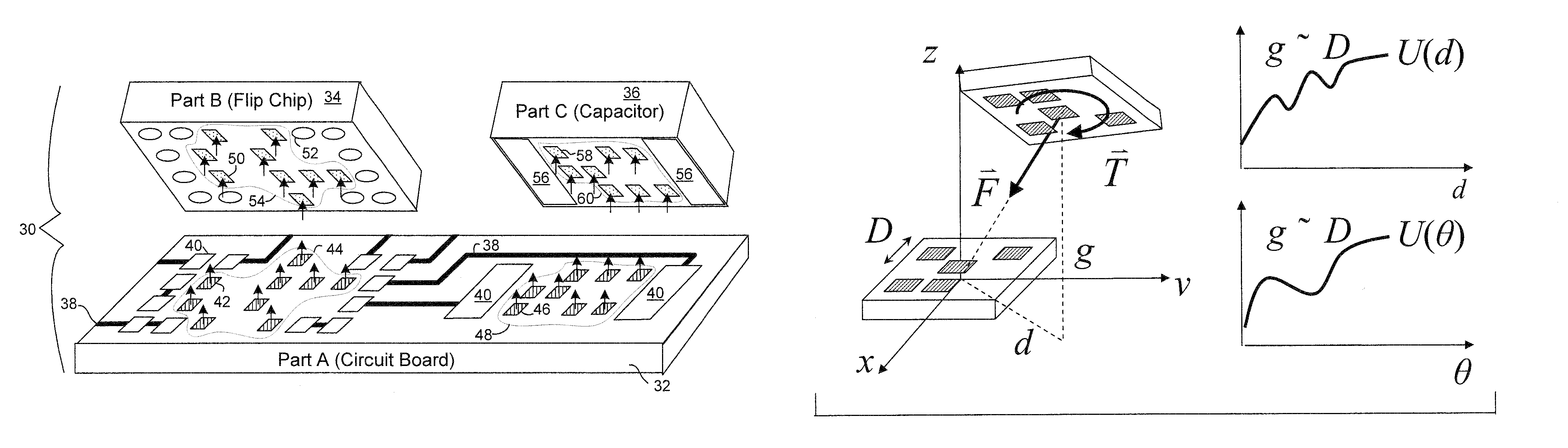
[0049]Reference is now made a specific embodiment, shown in FIG. 3, in which an assembly, generally indicated as 30, includes a first member 32, a second member 34 and a third member 36. First member 32 is a printed circuit board; the circuit having a generic flip chip circuit and capacitor by way of example mounted thereon. Circuit board 32 is provided with circuit structure including wiring or trace leads 38 conductively coupled to solder bumps 40 to allow electrical connection with other members 34, 36. Circuit board 32 (interchangeably referred to as first member 32) includes a first plurality of magnets 42 arranged in a pattern 44 to provide a shaped magnetic field. Circuit board 32 also includes a second plurality of magnets 46 arranged in a second pattern 48.

[0050]Second member 34, in this embodiment a flip chip, is formed with a plurality of magnets 50 thereon and solder bumps 52. Magnets 50 are provided in a predetermined pattern 54, which is the mirror image of pattern 44 ...


PUM

PropertyMeasurementUnit
thicknessaaaaaaaaaa
thicknessaaaaaaaaaa
thicknessaaaaaaaaaa

Abstract

A magnetically directed, self-assembled structure has a first body. The first body includes a single magnet or plurality of magnets disposed thereon to form a spatially variable magnetic field in a first predetermined pattern. A second body has a single magnet or plurality of magnets disposed thereon to form a spatially variable magnetic field in a second predetermined pattern. The second predetermined pattern is complementary to the first pattern. The first body is attracted to the second body with an attractive force greater than a mixture force such that the first body and second body are fully aligned to each other and bonded together.

Description

CROSS-REFERENCE TO RELATED APPLICATIONS[0001]This application is a continuation-in-part of International Patent Application No. PCT / US2006 / 045633, filed Nov. 28, 2006, which claims the benefit of U.S. Provisional Patent Application Ser. No. 60 / 740,139, filed Nov. 28, 2005, the disclosures of which are hereby incorporated by reference in their entirety.GOVERNMENT SUPPORT[0002]This work was supported in part from National Science Foundation Grant Nos. ECCS-0716139 and DMI-0556056. The government has certain rights to this invention.BACKGROUND OF THE INVENTION[0003]This invention is directed to the self-assembly of three-dimensional structures, and more particularly, to the self-assembly of three-dimensional structures for integrated circuits utilizing shaped magnetic fields.[0004]Over the past few decades, advances in the field of electronic and photonic devices for signal processing wireless communication, computing and the like have become more complex as they become more highly int...

Claims


Application Information

Patent Timeline
Patent Type & Authority Patents(United States)
IPC IPC(8): H01F7/00B23P19/00H01F1/00
CPCB81C1/00007H01L24/83H01L24/95H01L25/50H05K3/303B81C3/002Y10T29/4913H01L2224/83801H01L2224/95085H01L2224/95092H01L2224/95136H01L2224/95144H01L2224/95145H01L2924/01005H01L2924/01015H01L2924/01027H01L2924/01078H01L2924/01082H01L2924/01105H01L2924/14H01L2924/15155H01L2924/15165H01L2924/19041H01L2924/19042H01L2924/19043H01L2924/19105H01L2924/3025H05K2201/083H05K2201/10636H05K2201/10674H05K2203/048Y10T29/53196Y10T29/5313Y10T29/49075H01L2924/1461H01L2924/01033H01L2924/01006H01L2924/01023H01L2924/15153H01L2924/3512H01L2924/00H01L2224/95146Y02P70/50
Inventor ARNOLD, DAVID PATRICK
Owner UNIV OF FLORIDA RES FOUNDATION INC
Why Eureka
Try Eureka