Over the past few decades, advances in the field of electronic and photonic devices for
signal processing wireless communication, computing and the like have become more complex as they become more highly integrated.
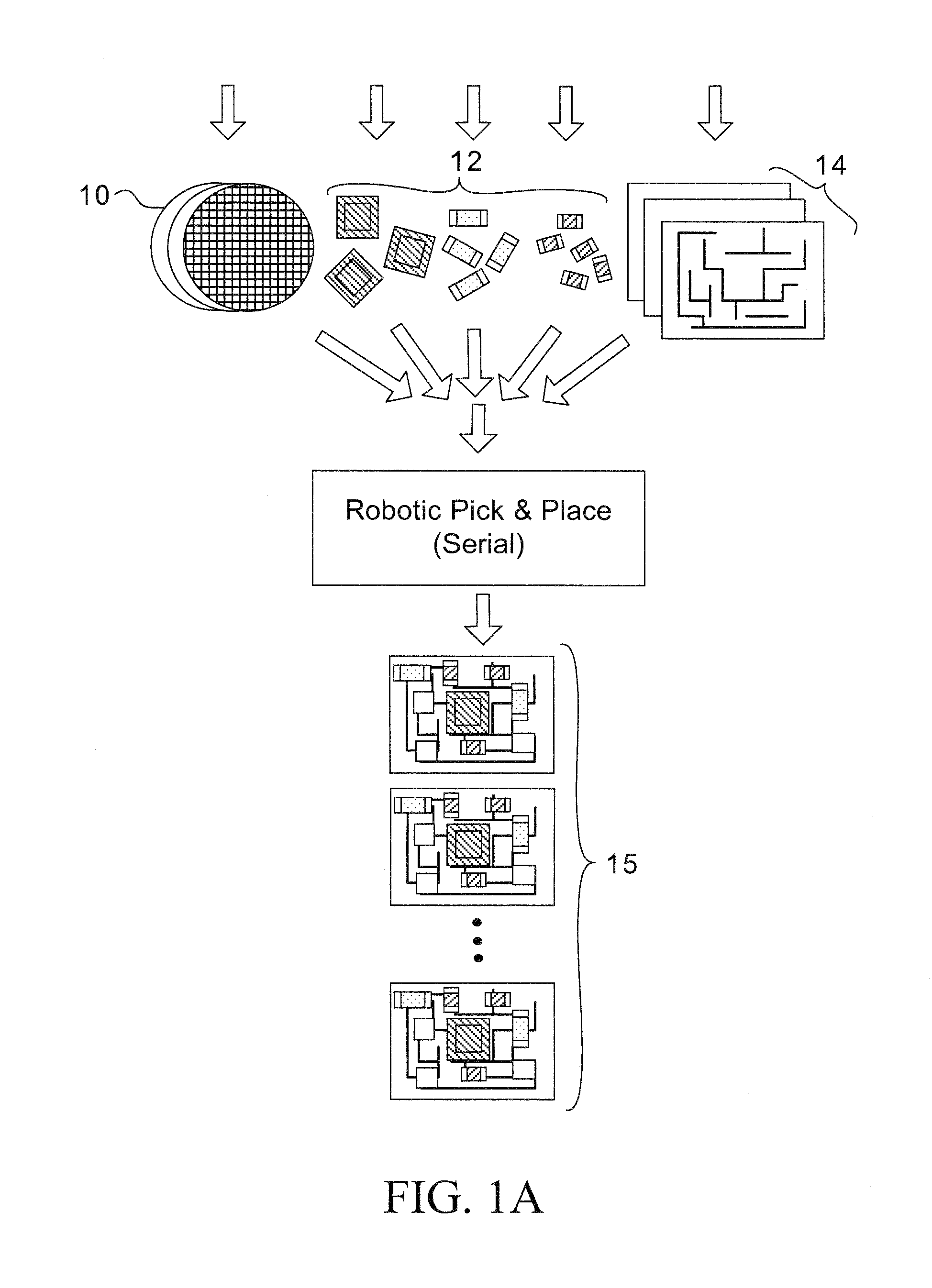
This method has been satisfactory; however, it suffers from the
disadvantage that the large number of components that can be batch manufactured overwhelm the
throughput capabilities for the serial back-end packaging and
assembly.
Because of the serial nature, the
throughput is limited by the number and speed of the robotic manipulators.
Secondly, the shrinking physical size of the
microelectronics, down to the micro- or nanoscale in many applications, requires precise manipulation.
Lastly, for sub-
millimeter parts, the adhesion forces between the part and the
manipulator are significant compared to gravity, resulting in a sticking problem.
This adds complexity to the structure of a substrate, is often substrate-limited, i.e., is too difficult to use between two free-floating bodies, and requires the input of energy.
However, in the prior art, the magnetic forces were the result of the entire structure being a
magnet where the structures were attracted to each other, but there is no control over selectivity, or interaction.
Furthermore, the magnetic approach was also limited to substrate bonding, not to free floating bodies.
These techniques and methods for manufacture have been satisfactory; however, they do not match the full functionality offered by robotic or human part manipulation such as orientational uniqueness, bonding selectivity, or inter-part bonding.
As a result, they limit the basic logical design rules available for a designer in the self-assembly process.
In other words, certain incorrect orientations may result in a local minimization of energy, and the mixing energy is insufficient to move the part into the desired orientation to achieve the
global energy minimum.
However, these approaches require parts with large scale asymmetrical physical geometries, adding cost and complexity to the batch manufacture process.
In the capillary driven self-assembly method, asymmetric bonding interfaces have been implemented, but the alignment precision decreased and the process yields dropped by nearly 70%.
The drop in yield is attributed to local energy minima creating misfits and the reduced precision was attributed to a less sharp dip in the energy curve.
Although allowing bonding selectivity, it requires substantial
processing and precludes parallel assembly of heterogeneous mixtures.
Furthermore, this sequential process lengthens the assembly process as a function of the number of different components.
However, the number of mutually exclusive shapes may be limited and
chip real estate may be wasted as a result of the need for size differentiation as one shape
differentiator.
Furthermore, the
machining of arbitrarily shaped parts imposes additional processing complexity and cost.
Therefore, the prior art provides no real solution for the bonding selectivity issue and the requirement in more complex applications for sequential selective bonding in a
parallel process.
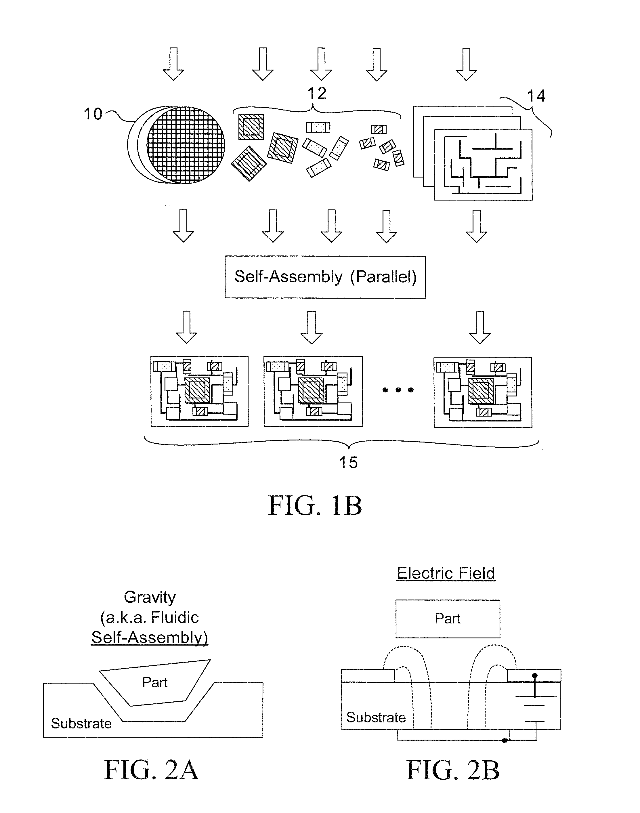
Because of this, gravity-driven processes are inapplicable because gravity only acts in one direction.
A secondary challenge for inter-part bonding is preventing agglomeration, where parts of a similar type inadvertently bond to each other rather than to the specified
receptor site.
As a result, capillary-driven assembly is inapplicable because agglomeration requires that there are no short range bonding forces between similar parts, while insuring there are bonding forces between dissimilar parts.
This process has been shown to have potential to be satisfactory, however, it suffers from the drawback that it requires sequential assembly steps and the limitation of a single electrical contact between the individual parts and the requirement for parts of dissimilar size to prevent agglomeration.

