Non-uniform image defect inspection method

a defect inspection and non-uniform technology, applied in image enhancement, image analysis, instruments, etc., can solve the problems of high quality requirements, inability to easily detect human eyes and ccd (charge-coupled device) cameras, and inability to achieve the same qualities of inspected lcd products. to achieve the effect of improving inspection efficiency

Active Publication Date: 2012-03-27
NAT TAIPEI UNIV OF TECH
View PDF10 Cites 16 Cited by
  • Summary
  • Abstract
  • Description
  • Claims
  • Application Information

AI Technical Summary

Benefits of technology

[0018]One object of the invention is to provide a non-uniform image defect inspection method, which replaces eyes-inspection with an inspection calculation based on image reconstruction to enhance the inspection efficiency.
[0019]Another object of the invention is to provide a non-uniform image defect inspection method, which can inspect different types of defects without any defect image template and can enhance the inspection speed.

Problems solved by technology

With the development of LCD technology, the requirement for quality has become highly demanding.
Even following the same inspection standard, different workers may have their own standards by using eyes-inspection method, and the same qualities of the inspected LCD products certainly cannot be reached.
A micro defect is a defect smaller than 100 mm and it cannot be easily detected by human eyes and CCD (Charge-coupled device) cameras.
Mura defects are generated when the brightness of the flat panel display is not uniform.
Mura defects are generated because of the following reasons: the thickness of the TFT is not uniform, the liquid crystal is not uniform, the gap forms between two glass substrate, the color filter is not uniform, and the light from the backlight module is not uniform.
Mura defects often are not uniform and have a low contrast.
So Mura defects have tiny brightness difference with their surrounding background and have non-uniform brightness changes.
It is difficult to inspect Mura defects because Mura defects have the low contrast and un-uniform brightness changes, and images displayed on LCD have un-uniform brightness variation.
If Mura defects are inspected with human eyes, it may be very time-consuming and cannot always maintain a constant quality standard.
It is difficult to inspect Mura defects because of non-uniform brightness distribution of an LCD image.
It is difficult to inspect the defects even by extracting the defects through image binarization.
It is easy to detect defects with clear edges by using the space-domain analysis method; however, it is difficult to detect defects with unclear edges such as Mura defects by using the space-domain analysis method.
DFT is always performed with complex number and complex calculation, and it needs a sample image without any defect as an inspection standard, which will reduce the inspection speed.
Except for flat panel display production, non-uniform brightness defects inspection is also needed in other industries.
A ball or a bump whose height is lower than others may cause open circuit on the PCB.
Alternatively, a ball or a bump whose height is higher than others may cause short circuit on the PCB.
Since the image difference could be undiscoverable and the brightness of the background image could be non-uniform, it is also difficult to inspect defects on a PCB with X-ray tomography.

Method used


Image

  • Non-uniform image defect inspection method
  • Non-uniform image defect inspection method
  • Non-uniform image defect inspection method

Examples


embodiment 1

the Non-Uniform Background of the Original 2D Image

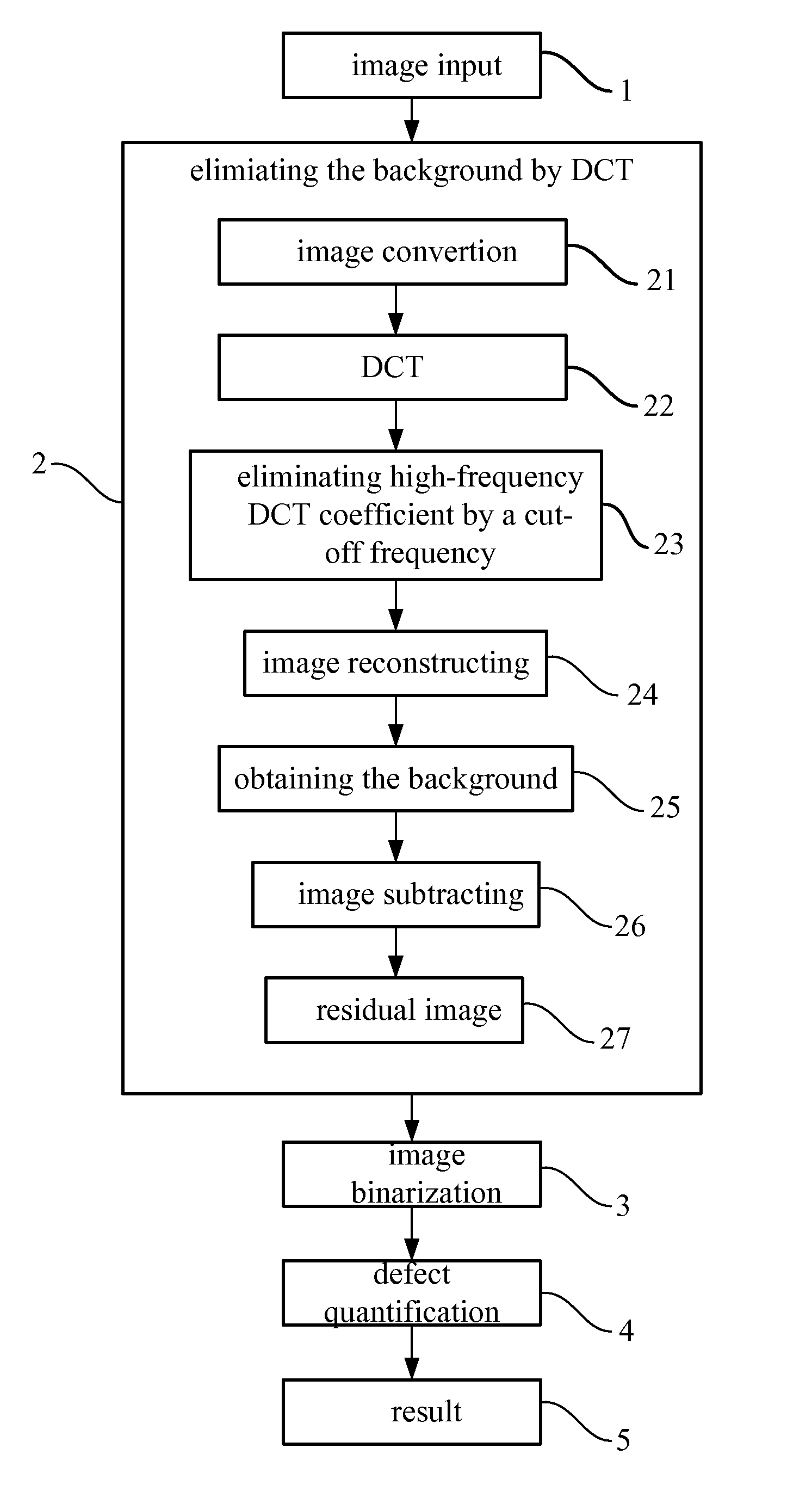
[0047]In the invention, the input image is converted from space domain to frequency domain by a 2D DCT which is defined as the formula 1:

[0048]C⁡(u,v)=α1⁡(u)⁢α2⁡(v)⁢∑x=0M-1⁢⁢∑y=0N-1⁢⁢f⁡(x,y)⁢cos⁡[π⁡(2⁢x+1)⁢u2⁢M]⁢cos⁡[π⁡(2⁢y+1)⁢v2⁢N](1)

[0049]Wherein the original image is denoted as M×N which can be adjusted according to a demanded resolution of the inspector;

[0050]f(x,y) denotes the input information;

[0051]C(u,v) denotes the output DCT coefficients;

[0052]x=0,1,2,…⁢,M-1;y=0,1,2,…⁢,N-1;u=0,1,2,…⁢,M-1;v=0,1,2,…⁢,N-1;α1⁡(u)={1M⁢⁢for⁢⁢u=02M⁢⁢⁢for⁢⁢u≠0.⁢⁢α2⁡(v)={1N⁢⁢for⁢⁢v=02N⁢⁢⁢for⁢⁢v≠0.

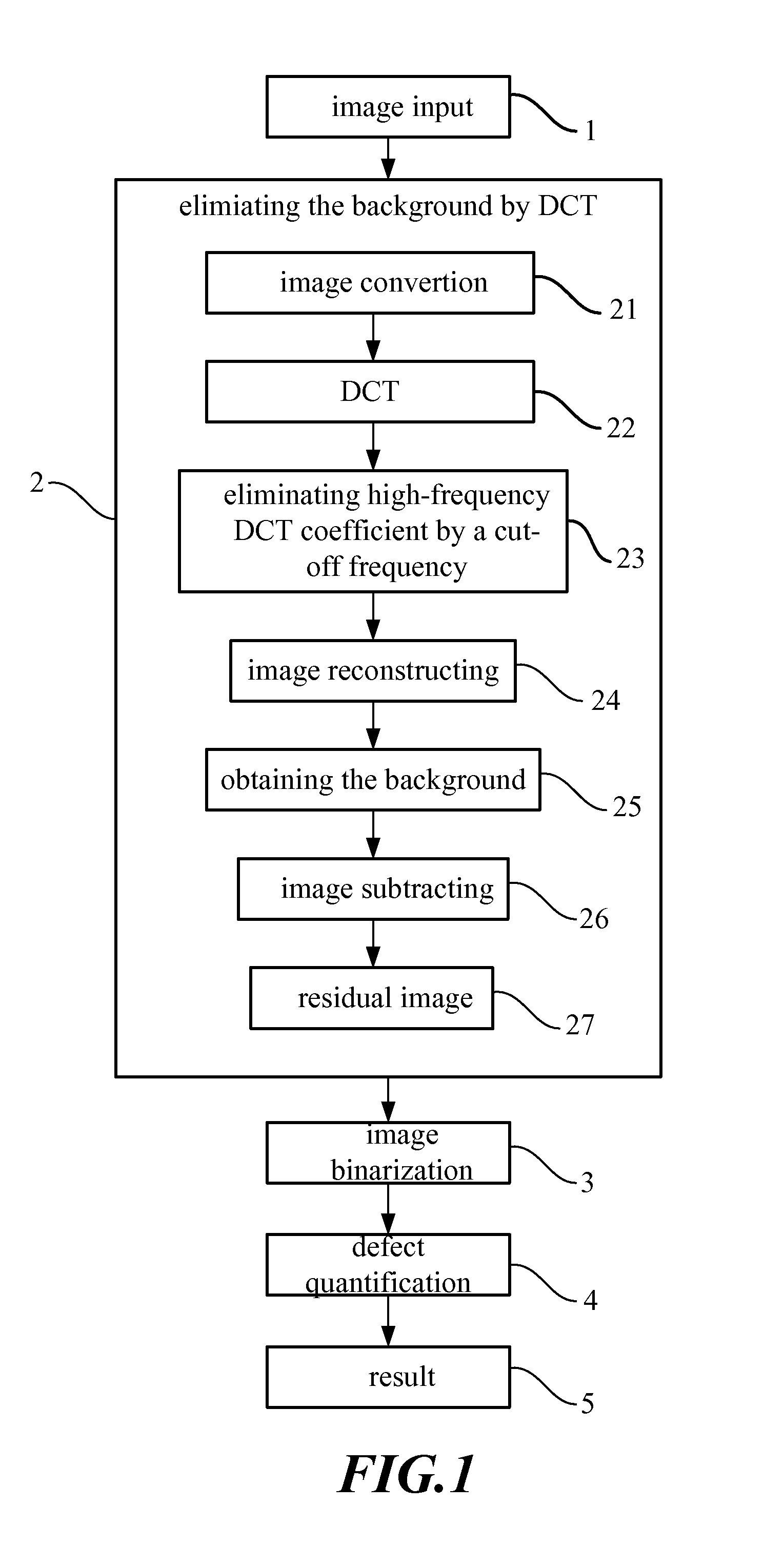
[0053]The 2D DCT describes an original image with a plurality of 2D fundamental image arrays. A 2D fundamental image array is a product of a vertical fundamental array and a horizontal fundamental array, as shown in formula 2. With different u or different v, a fundamental array image has different brightness. The bigger u or v is, the higher the changing ...

embodiment 2

zation

[0064]After reconstruction by DCT, the residual image is performed using an image binarization. In this embodiment, the image binarization is a maximum entropy method. The maximum entropy method is applied to obtain an optimal threshold that is utilized to segment defects from the background image. The image regions whose brightness is higher than the optimal threshold are defined as defect regions, and the image regions whose brightness is lower than the optimal threshold are defined as background regions. Then a gray value of the defect is set to 255, and a gray value of the background is set to 0. In addition, any other binarization operation can be used as the image binarization.

[0065]According to the second law of thermodynamics, when a system is on a uniform disorder state, the entropy of the system is the maximum. As a function, the entropy is utilized to denote the disorder grade of a system. If the incident probability is average distributed, the entropy is a negative...

embodiment 3

tation

[0070]The image performed an image binarization may include some non-uniform regions. To segment each individual non-uniform image defect region, an image segmentation is performed and each individual non-uniform image defect region is labeled with a unique codeword. In this embodiment, each pixel is regarded as a seed, and image segmentation is performed by searching pixel to pixel from the original pixel on the left corner, by way of that from left to right and from top to bottom. FIG. 5 shows the procedure of the image segmentation. Assuming that the gray value of the dark points in the binarization image is 0, and the gray value of the bright points (defects) is 255. The procedure is started by searching for a first bright point which is regarded as a seed (shown in FIG. 5A). Then, label the seed with a codeword A, and perform a region growing operation based on four neighbors or eight neighbors to search pixels that are bright points and connected with the seed. As shown ...


PUM


Abstract

A non-uniform image defect inspection method includes steps of inputting an original two-dimensional image; separating a non-uniform background image from the original two-dimensional image by Discrete Cosine Transform (DCT) to obtain a residual image without the non-uniform background image; binarization segmenting the residual image to extract defects from the residual image, wherein the segmented defects are the inspection results.

Description

FIELD OF THE INVENTION[0001]The invention relates to a non-uniform image defect inspection method, especially to a non-uniform image defect inspection method that can extract non-uniform image defects from the inspected image by way of reconstructing an original background image without defects by Discrete Cosine Transform (DCT) and selecting an appropriate threshold.DESCRIPTION OF THE RELATED ART[0002]Display apparatuses are main interfaces for message delivery and communication. Flat panel displays become more popular because they are light, thin and portable, and they consume low energy. Flat panel displays have been developed to many types such as PDP (Plasma Display Panel), LED (Light Emitting Diode), OLED (Organic Light Emitting Diode) and LCD (Liquid Crystal Display) from CRT (Cathode Ray Tube) which occupies a large space, wherein TFT (Thin Film Transistor) LCD technology is most matured. In recent years, TFT LCD has become a mainstream of displays and been widely used. The ...

Claims


Application Information

Patent Timeline
Patent Type & Authority Patents(United States)
IPC IPC(8): G06K9/40G06K9/36G06K9/00
CPCG06T7/0004G06T2207/30121
Inventor CHEN, LIANG-CHIAKUO, CHIA-CHENG
Owner NAT TAIPEI UNIV OF TECH
Why Eureka
Try Eureka