Modular wind turbine system

a wind turbine and module technology, applied in the direction of machines/engines, electric generator control, greenhouse gas reduction, etc., can solve the problems of mechanical stress induced on the blading and support structure, the inability to fabricate a cost-effective method, and the inability to balance the blading on the support structure. , to achieve the effect of improving the power output, improving the stability of the blade, and improving the overall stability of the blad

Active Publication Date: 2012-04-03
APTHORP SCOTT
View PDF23 Cites 6 Cited by
  • Summary
  • Abstract
  • Description
  • Claims
  • Application Information

AI Technical Summary

Benefits of technology

[0017]These, and other, advantages are achieved by the system embodying the present invention in which improved power output of as much as 10 to 15 times that of a normal windmill with an added benefit of blade stability in drastic wind velocity changes is realized by using an outer blade edge of a stacked blade configuration windmill to generate electricity through outside rings which includ

Problems solved by technology

While these devices have been successfully employed for many hundreds of years, there still remain major unresolved technical problems in the design of conventional wind turbines which make them problematic for small and large scale energy production.
To date no practical cost-effective method exists for fabricating ducted shrouds, much less balance them on support structures.
Mechanical stresses induced on the blading and support structure present further limitations especially for large windmills.
These mechanisms proposed to date make the blades fragile and costly.
Furthermore, large diameter blades, such as over 100 feet in length, present significant dynamic stress problems.
Long blades supported at their roots and under the influence of the aforementioned oscillating forces are subjected to an increasingly severe and complex system of dynamic instabilities.
It is difficult and expensive to safeguard against such instabilities.
Although these generators are commonly available, they represent a one hundred year old technology that has not incorporated recent technological breakthroughs in material science, power control and aerodynamics.
These generators, while compact, are heavy because of the massive laminated iron core and copper windings.
It is well known now that the change of wind momentum by aerodynamic forces on the rotor blades is limited in energy output by several factors.
First, the ideal efficiency is limited to about 0.593 of the wind power per unit area by the unavoidable shedding of flow around the tip of the rotor.
Secondly, occasional extremes of wind speeds can lead to destruction of the rotor blades, unless controls be employed to reduce the geometric obstruction presented by the rotor.
This control measure limits maximum output to be expected from a wind turbine.
Thirdly, the aerodynamics of the tower supporting the wind driven rotor must be taken into account in the design of the blades whether located ahead of or behind the rotor to the determent of structural cost to accommodate the aerodynamic loading such structures create.
Thus, over the years, many groups have become interested in the diffuser-augmented windmills, but they have always dropped the idea because the diffuser ha

Method used


Image

  • Modular wind turbine system
  • Modular wind turbine system
  • Modular wind turbine system

Examples


Embodiment Construction

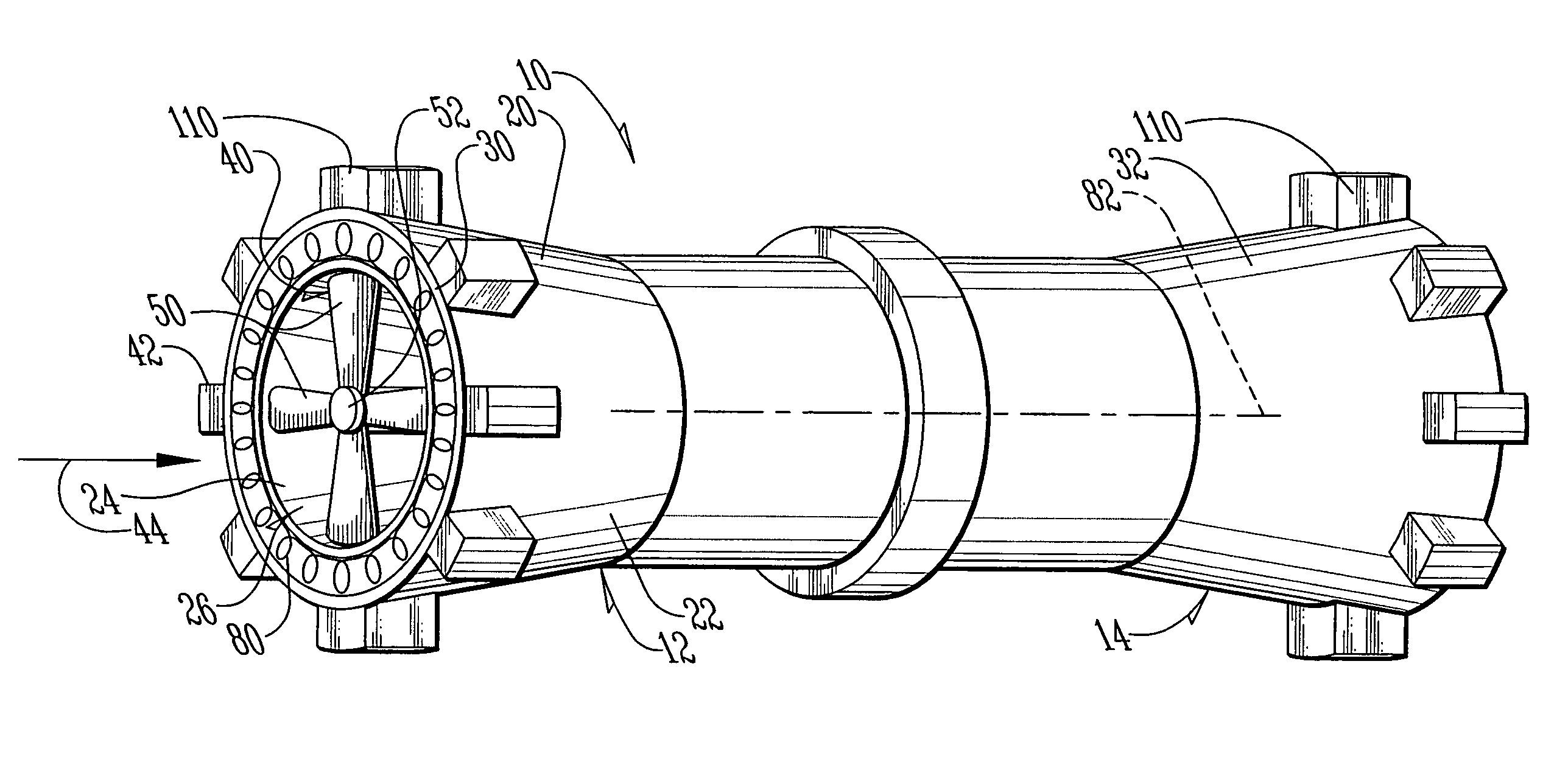
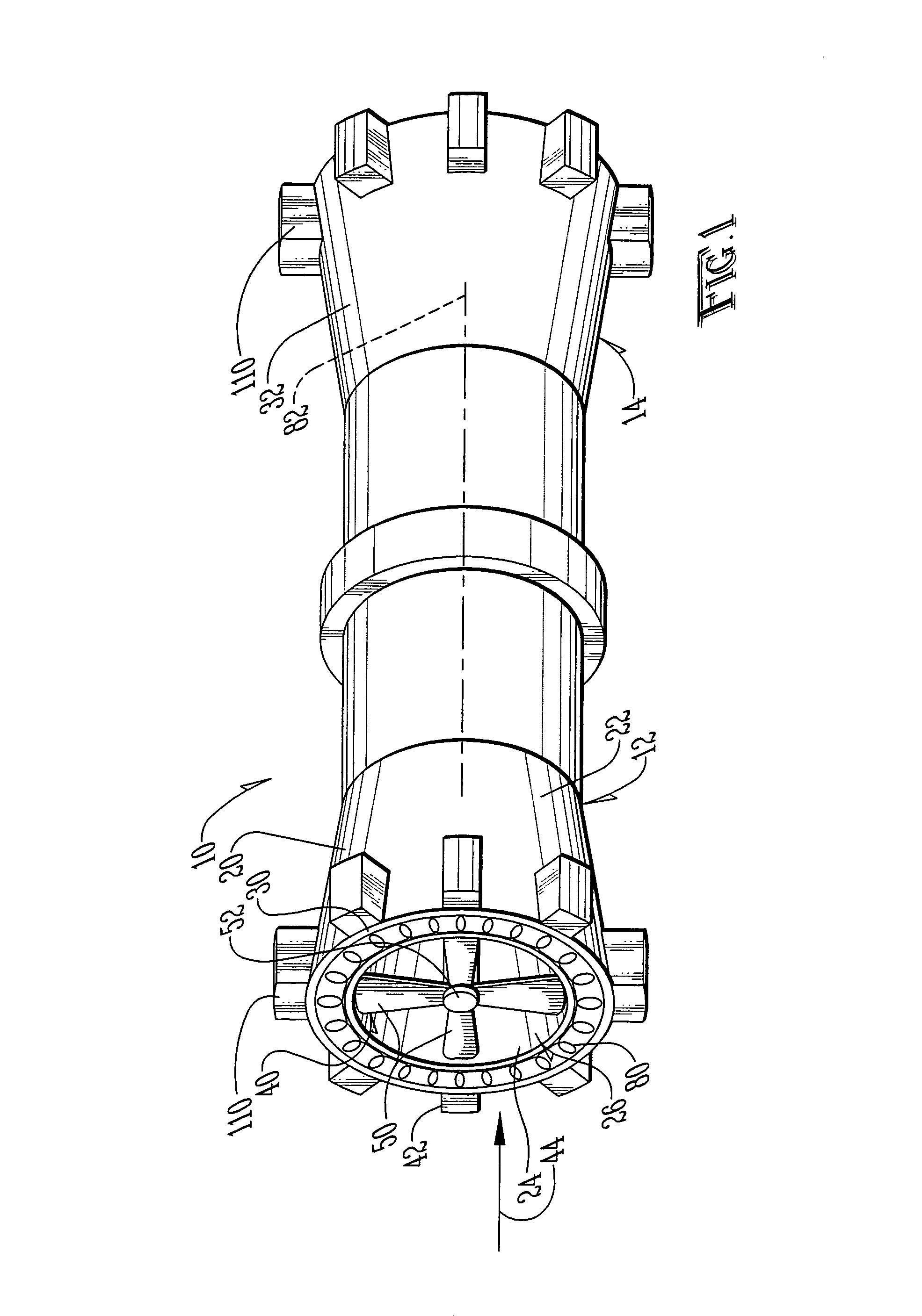
[0025]Referring to the figures, it can be understood that the present invention is embodied in a windmill 10 which can be used in conjunction with various powered systems, including, but not limited to, static structures, such as houses or the like, vehicles, such as automobiles or the like and other such systems. System 10 is modular so it can be sized according to the requirements of the system being powered. Two modules 12 and 14 are shown in FIG. 1, but this should be considered as being an example only and more modules can be used as required without departing from the scope of this disclosure. Windmill 10 includes an outer casing 20 which can be sized and shaped in accordance with the requirements of the system and in accordance with the requirements of the airflow through the system. The shape shown in FIG. 1 is a converging / diverging shape, but other shapes can be used as well.

[0026]Outer casing 20 includes an outer surface 22 and an inner surface 24 which defines a bore 26 ...


PUM


Abstract

A windmill includes a rotor having an outer blade edge of a stacked blade configuration windmill which generates electricity through outside rings which include wire windings. The outer blade edges are configured in a C-shape to enclose as much as ¾ of the outside ring to give mounting areas and overall blade stability. The system can be mounted in vehicles to charge batteries or provide for hydrogen separation in hydrogen cars as well as many other applications. The system can be modular so that a windmill of any suitable size can be constructed.

Description

TECHNICAL FIELD OF THE INVENTION[0001]The present invention relates to the general art of power generation, and to the particular field of windmills.BACKGROUND OF THE INVENTION[0002]A background summarization of the utilization of wind for generating electrical power has been documented in a NASA publication entitled “The Development of Wind Powered Installations For Electrical Power Generation In Germany”, U. Hutter, NASA TTF-15,050 National Aeronautical and Space Administration, Washington, D.C. 20546, August 1973. Suffice it to say, one of the oldest methods of extracting energy from fluids in motion is by means of bladed rotating machines such as, for example, windmills exposed to the wind and hydro impellers powered by the fluid reaction of moving water. A history of the development of wind energy is presented by the publication entitled, “Wind Energy Developments In The Twentieth Century”, published by the Lewis Research Center of the National Aeronautics and Space Administrat...

Claims


Application Information

Patent Timeline
IPC IPC(8): F03B13/10
CPCF03D9/00F05B2220/61F05B2240/133F05B2240/941Y02E10/72Y02E70/10Y02E10/728F03D9/25F03D9/32F03D9/34F03D9/11F03D80/00F03D13/10B60K16/00Y02E60/36Y02E70/30
Inventor APTHORP, SCOTT
Owner APTHORP SCOTT
Why Eureka
Try Eureka