
Communication system, communication device, communication method, and program

a communication system and communication method technology, applied in the field of wireless communication, can solve the problem of reducing the power usable for shared data channels, and achieve the effect of reducing the information content of control channels

Inactive Publication Date: 2012-04-10
NTT DOCOMO INC
View PDF10 Cites 5 Cited by
  • Summary
  • Abstract
  • Description
  • Claims
  • Application Information

AI Technical Summary

Benefits of technology

[0012]Embodiments of the present invention make it possible to reduce the information content of control channels used for multiplex transmission of a large number of small-sized packets.

Problems solved by technology

This in turn increases the share of the total transmission power of the base station to be allocated to shared control channels and therefore decreases the power usable for the shared data channel.

Method used


Image

  • Communication system, communication device, communication method, and program
  • Communication system, communication device, communication method, and program
  • Communication system, communication device, communication method, and program

Examples


first embodiment

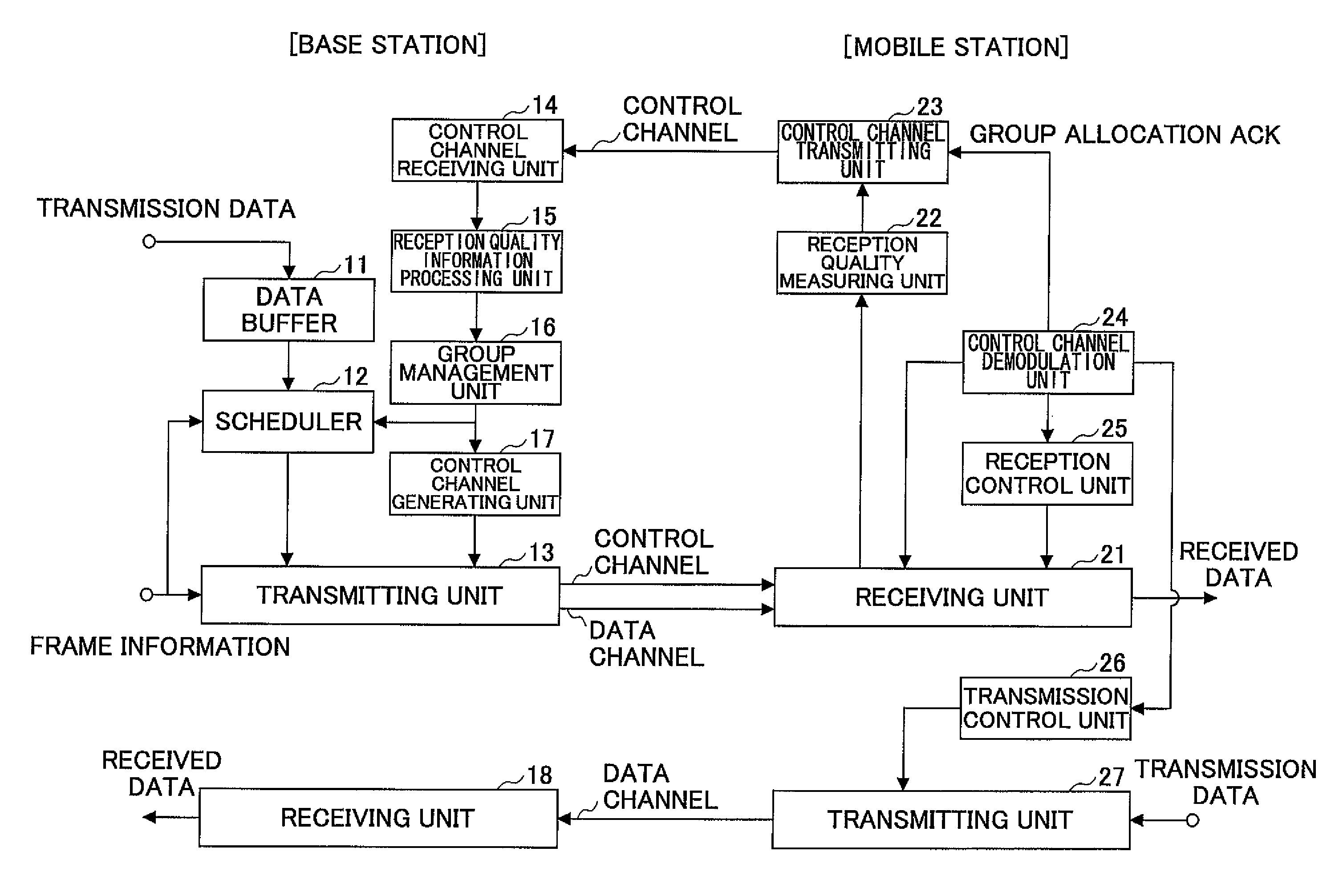
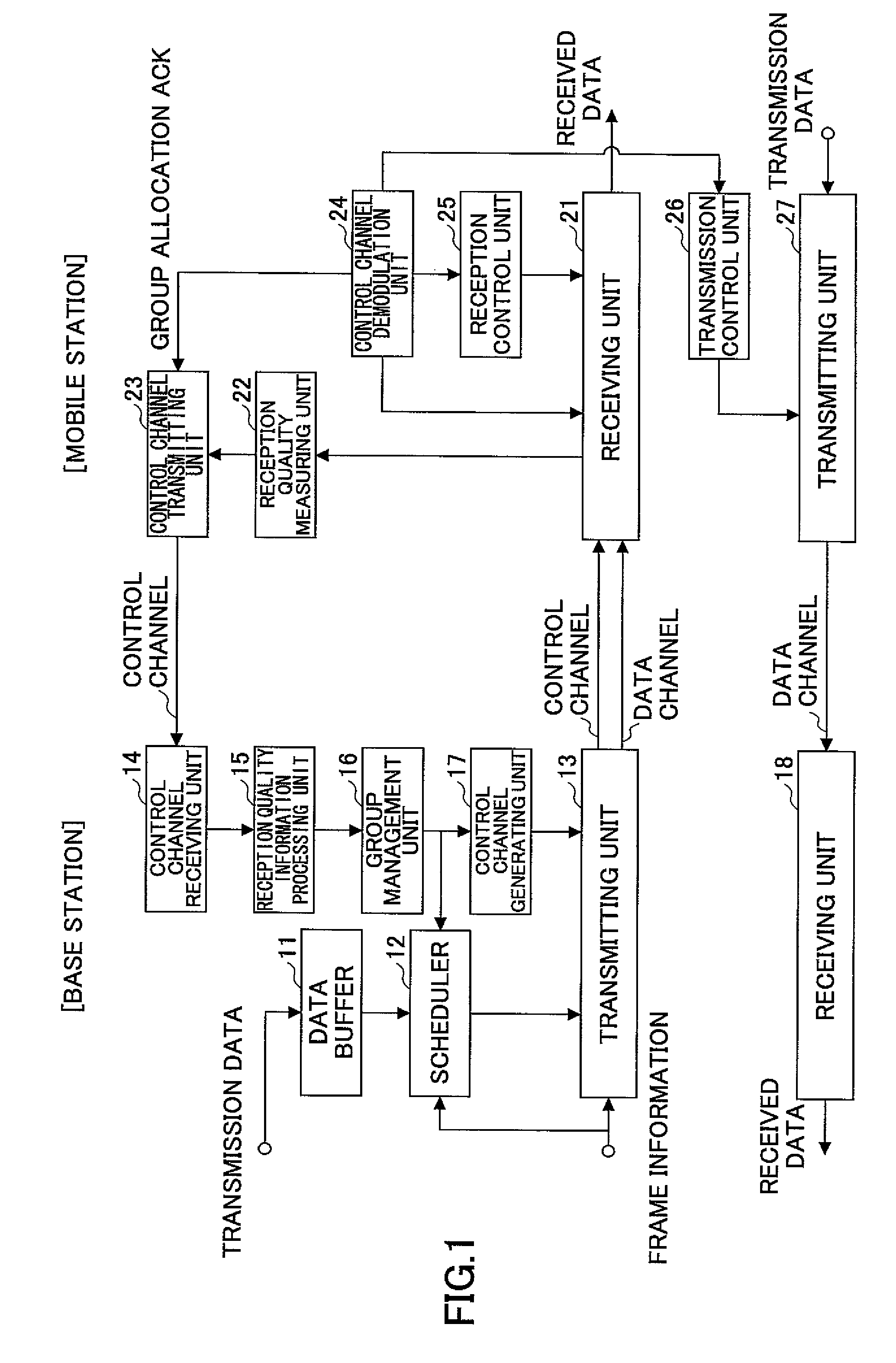
[0033]FIG. 1 is a drawing illustrating a base station and a mobile station used in a communication system according to an embodiment of the present invention. The base station includes a data buffer 11, a scheduler 12, a transmitting unit 13, a control channel receiving unit 14, a reception quality information processing unit 15, a group management unit 16, a control channel generating unit 17, and a receiving unit 18.

[0034]The data buffer 11 stores transmission data for mobile stations.

[0035]The scheduler 12 determines mobile stations to which frequency and / or time resources are to be allocated and the timings of allocating the resources. Different from conventional devices or methods, the scheduler 12 performs scheduling taking into account frame information and group information as described later.

[0036]The transmitting unit 13 transmits a scheduled shared data channel in a format indicated by the frame information. The transmitting unit 13 also transmits control channels generat...

second embodiment

[0056]FIG. 4 is a set of flowcharts showing an exemplary process for changing the group of a mobile station. In FIG. 4, steps S11 through S15 performed by the base station and steps S21 through S25 performed by the mobile station are shown in parallel. At the beginning of communication, the base station transmits, to the mobile station, information on a frame format, information on the correspondence between groups and subframes, and information indicating the initial group of the mobile station (S11). The mobile station receives the pieces of information and prepares for the communication (S21).

[0057]Then, the mobile station reports the current received signal quality to the base station (S22).

[0058]The base station monitors the signal quality reported by the mobile station (S12) and determines whether to change the group to which the mobile station belongs. This is because the communication condition of the mobile station may change as time passes. The signal quality may be repres...


PUM


Abstract

A disclosed communication system includes a base station and mobile stations. The base station includes a group management unit configured to classify the mobile stations into groups according to signal quality information transmitted from the mobile stations, a storing unit configured to store correspondence information on the correspondence between the groups and subframes constituting at least a part of a radio frame, a scheduling unit configured to schedule packets for the mobile stations according to the correspondence information, and a transmitting unit configured to transmit the correspondence information to the mobile stations. Each mobile station includes a transmitting unit configured to transmit the signal quality information indicating received signal quality to the base station, and a receiving unit configured to receive the packets transmitted from the base station in one of the subframes that corresponds to one of the groups to which the mobile station belongs.

Description

TECHNICAL FIELD[0001]The present invention generally relates to the field of wireless communication. More particularly, the present invention relates to a communication system, a communication device, a communication method, and a program.BACKGROUND ART[0002]The high speed downlink packet access (HSDPA) is a packet transmission method of IMT-2000 and is currently employed to implement a high-speed, high-capacity downlink. In HSDPA, scheduling is performed to allocate channel resources preferentially to users in good channel conditions and thereby to improve the throughput. For this purpose, a shared control channel (HS-SCCH) for reporting scheduling information and transmission schemes is provided along with a shared data channel (HS-DSCH). Because the scheduling information differs depending on the user, it is necessary to provide the same number of shared control channels (HS-SCCH) as the number of concurrent users. HSDPA is described, for example, in non-patent document 1.[0003]G...

Claims


Application Information

Patent Timeline
Patent Type & Authority Patents(United States)
IPC IPC(8): H04W4/00H04L47/22H04M3/00H04W4/06H04W28/00H04W28/16H04W28/18H04W72/04H04W72/08H04W72/12
CPCH04L1/0003H04L1/0009H04L1/0025H04W72/085H04L1/0026H04W72/1231H04L1/1671H04W72/0446H04W72/542H04W72/12H04L1/00H04W72/54
Inventor HARADA, ATSUSHIABETA, SADAYUKI
Owner NTT DOCOMO INC
Learn More