Nanofiber spinning method and device
a spinning method and yarn technology, applied in the field of yarn spinning methods and devices, can solve the problems of inability to achieve high productivity, and achieve the effects of high productivity, high strength and high strength
- Summary
- Abstract
- Description
- Claims
- Application Information
AI Technical Summary
Benefits of technology
Problems solved by technology
Method used
Image
Examples
first embodiment
[0092](First Embodiment)
[0093]Firstly, first embodiment of a nanofiber spinning device according to the present invention will be described with reference to FIG. 1 to FIG. 4.
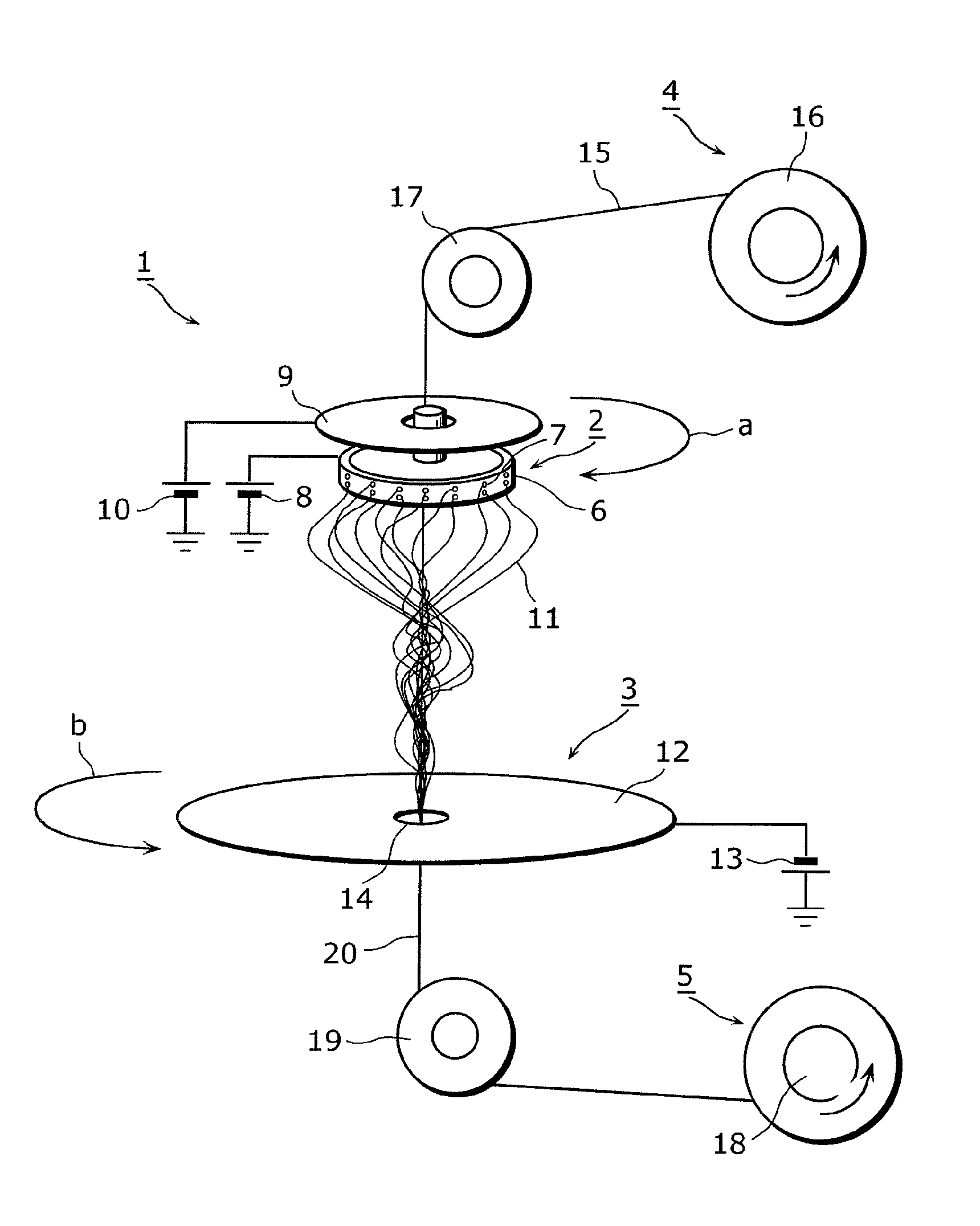
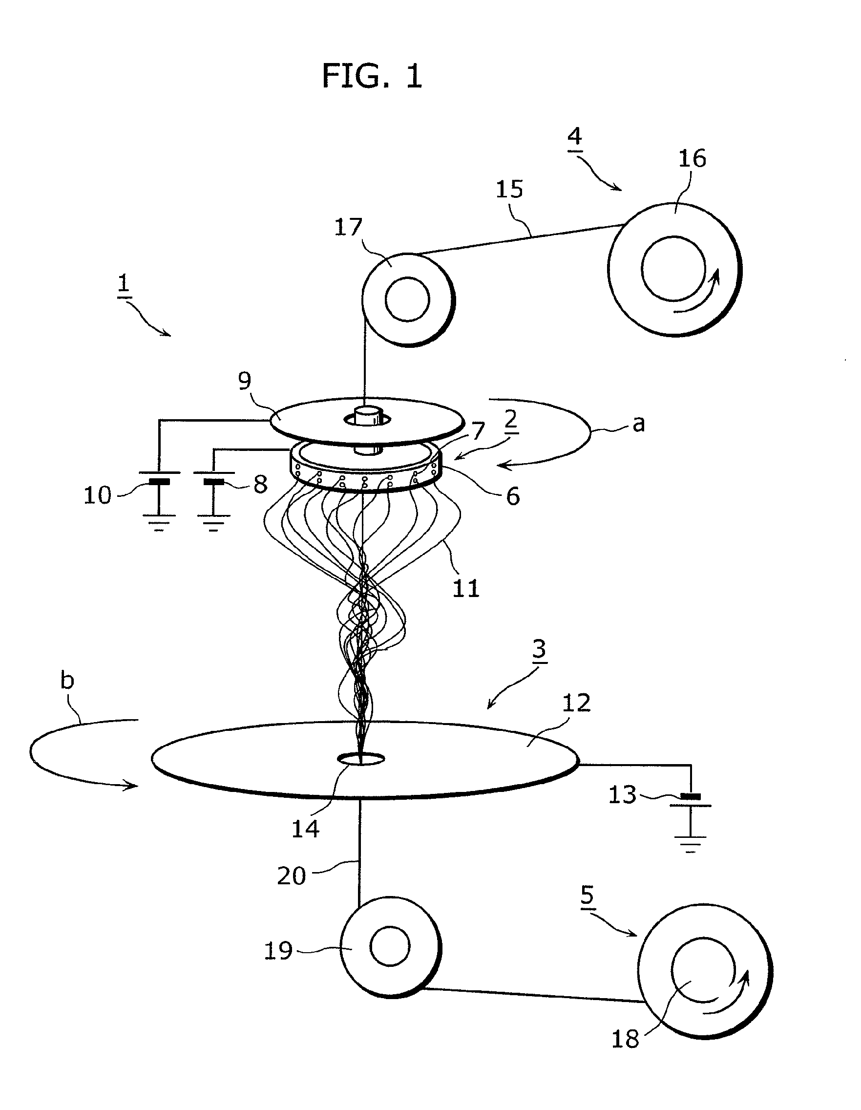
[0094]FIG. 1 is a perspective view of an overall schematic structure of a nanofiber spinning device 1 according to the first embodiment of the present invention.
[0095]The nanofiber spinning device 1 is a device which produces nanofibers and rotates the produced nanofibers for spinning. As shown in FIG. 1, the nanofiber spinning device 1 includes a nanofiber producing unit 2, a collecting electrode unit 3, a core yarn feeding unit 4, and a collecting unit 5.
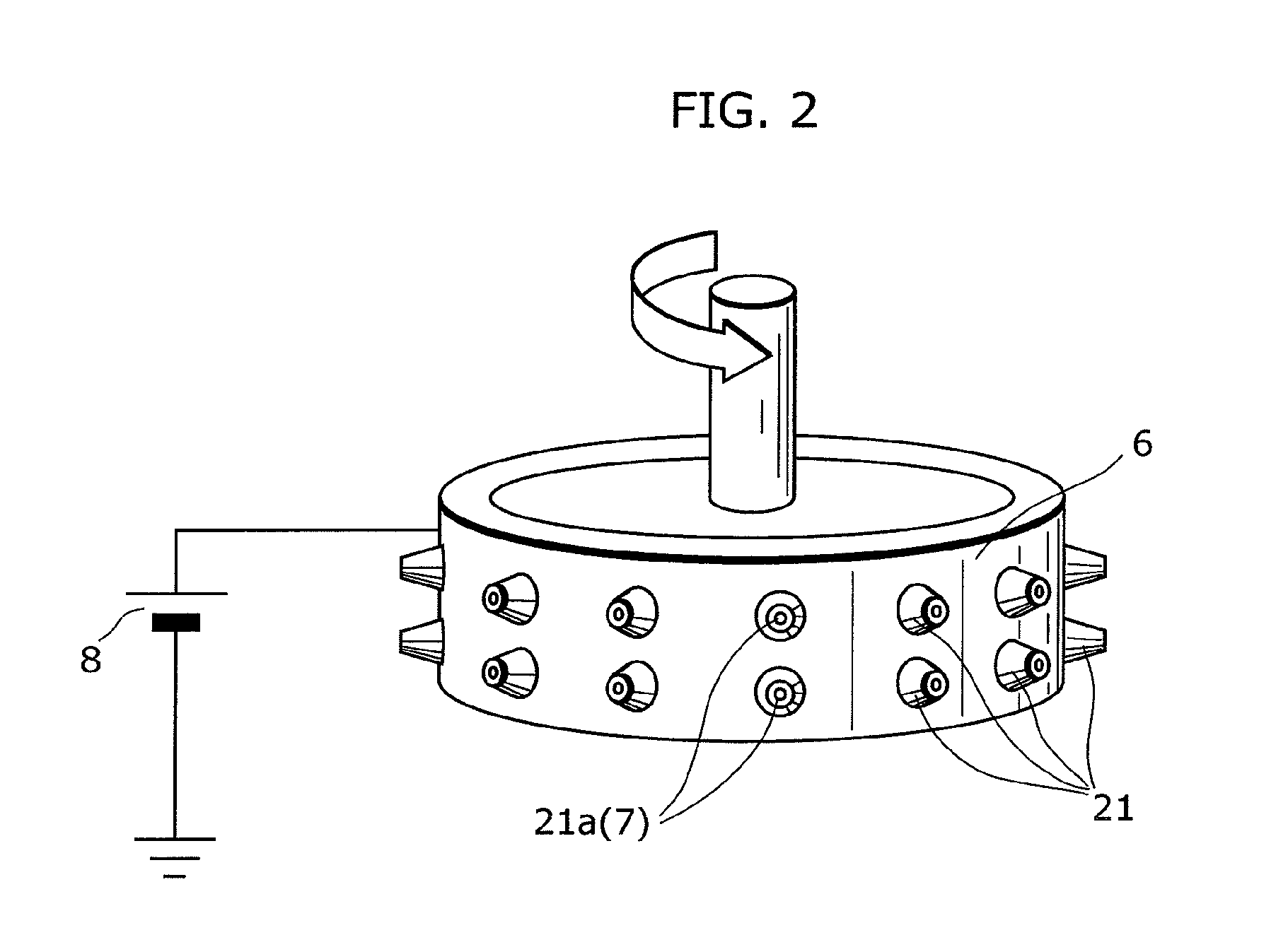
[0096]The nanofiber producing unit 2 includes a cylindrical container 6, a first high voltage generating unit 8, a reflecting electrode 9, and a second high voltage generating unit 10.
[0097]The cylindrical container 6 is a rotary container which is pivotally supported about its vertical central axis. The cylindrical container 6 has an outer circumferential su...
second embodiment
[0138](Second Embodiment)
[0139]Next, second embodiment of a nanofiber spinning device 1 according to the present invention is described with reference to FIG. 6 and FIG. 7. Note that in the following descriptions of embodiments, identical reference numerals are assigned to elements identical to those described in the previous embodiment, and descriptions thereof are omitted. Only differences from the previous embodiment are mainly described.
[0140]FIG. 6 is a longitudinal elevation view of an overall schematic structure of a nanofiber spinning device 1 according to second embodiment of the present invention.
[0141]In the first embodiment, an example has been described where a core yarn feeding unit 4, a nanofiber generating unit 2, a collecting electrode unit 3, and a collecting unit 5 are provided in a vertical direction from the top to the bottom in the mentioned order, a cylindrical container 6 and a collecting electrode 12 are rotated about the vertical central axis, and produced ...
third embodiment
[0156](Third Embodiment)
[0157]Next, third embodiment of a nanofiber spinning device according to the present invention will be described with reference to FIG. 8 to FIG. 12.
[0158]FIG. 8 is a perspective view of an overall schematic structure of a nanofiber spinning device 1 according to the third embodiment of the present invention.
[0159]In the first embodiment described above, as an example of the structure of the collecting electrode unit 3, the collecting electrode 12 is rotated; however, in the present embodiment, as shown in FIG. 8, a rotating electric field generating unit 45 is provided for generating, around the through-hole 14, a rotating electric field.
[0160]FIG. 9 is a perspective view of a schematic structure of a collecting electrode unit 3 according to the third embodiment of the present invention.
[0161]FIG. 10 is a phase diagram showing voltages applied to each divided electrode in the collecting electrode unit 3.
[0162]As shown in FIG. 9, the rotating electric field g...
PUM
| Property | Measurement | Unit |
|---|---|---|
| diameter | aaaaa | aaaaa |
| voltage | aaaaa | aaaaa |
| voltage | aaaaa | aaaaa |
Abstract
Description
Claims
Application Information
 - R&D
- Intellectual Property
- Life Sciences
- Materials
- Tech Scout
- Unparalleled Data Quality
- Higher Quality Content
- 60% Fewer Hallucinations
Browse by: Latest US Patents, China's latest patents, Technical Efficacy Thesaurus, Application Domain, Technology Topic, Popular Technical Reports.
© 2025 PatSnap. All rights reserved.Legal|Privacy policy|Modern Slavery Act Transparency Statement|Sitemap|About US| Contact US: help@patsnap.com


