Eureka AIR delivers breakthrough ideas for toughest innovation challenges, trusted by R&D personnel around the world.

Electrode manufacturing apparatus and electrode manufacturing method

a manufacturing apparatus and electrode technology, applied in the direction of superimposed coating process, liquid/solution decomposition chemical coating, cell components, etc., can solve the problems of uneven remaining on the backup roll, difficult to form electrodes with favorable planarity, etc., to improve the planarity further increase, facilitate the effect of keeping smoothness and favorable planarity

Active Publication Date: 2012-04-24
TDK CORPARATION
View PDF3 Cites 10 Cited by
  • Summary
  • Abstract
  • Description
  • Claims
  • Application Information

AI Technical Summary

Benefits of technology

[0007]In view of the problem mentioned above, it is an object of the present invention to provide an electrode manufacturing apparatus and electrode manufacturing method which can achieve an electrode having a current collector with a plurality of through holes and exhibiting favorable planarity.
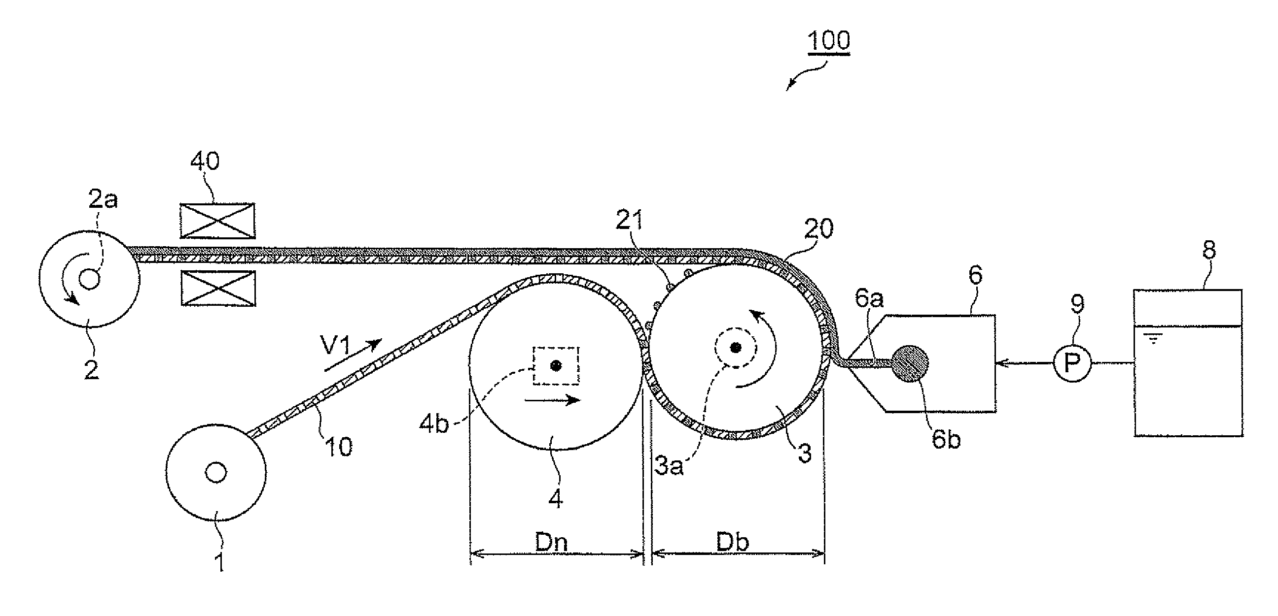
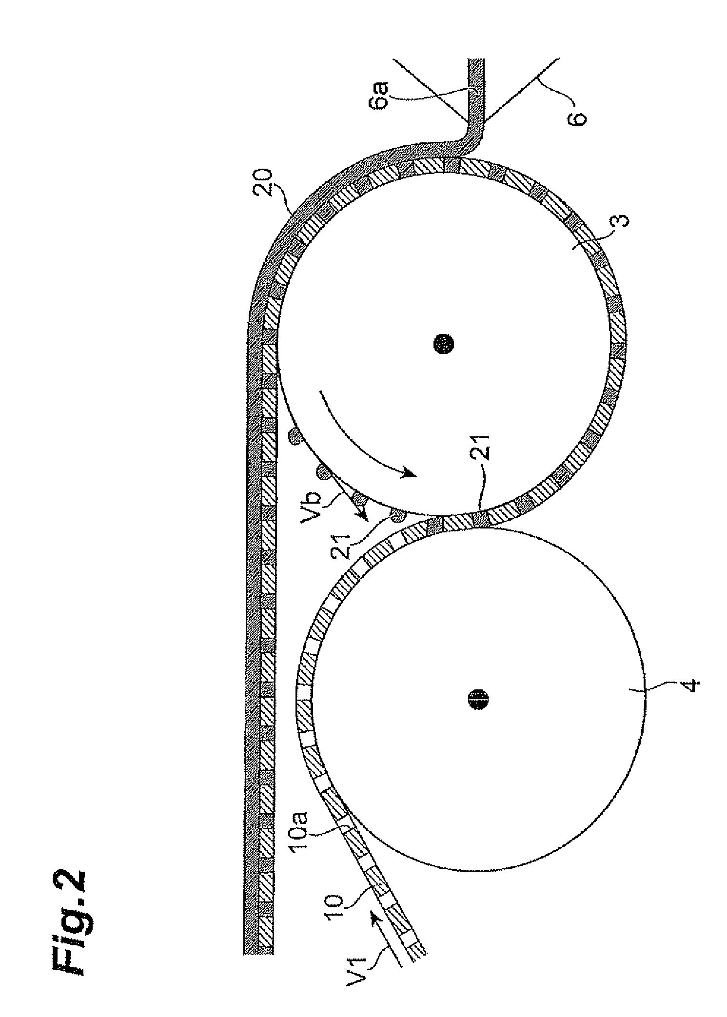
[0012]In this case, the moving speed of the surface of the backup roll differs from that of the current collector sheet, thereby causing a shear effect which further enhances the effect of pushing the coating liquid remaining on the backup roll into the through holes of the current collector sheet.
[0014]In this case, the surface of the current collector sheet to be coated with the coating liquid after pushing the coating liquid remaining on the backup roll into the through holes by the shear effect etc. is easier to keep its smoothness, whereby the effect of improving the planarity further increases.
[0015]The present invention provides an electrode manufacturing apparatus and electrode manufacturing method which can achieve an electrode having a current collector with a plurality of through holes and favorable planarity.

Problems solved by technology

When applied to the current collector sheet having a plurality of through holes, however, the coating liquid may reach the rear face through the through holes, thereby unevenly remaining on the backup roll.
As a consequence, subsequently supplied uncoated current collector sheets may incur uneven surface heights or their rear faces may bear flecks of coating liquid films, thus making it hard to form electrodes with favorable planarity.

Method used


Image

  • Electrode manufacturing apparatus and electrode manufacturing method
  • Electrode manufacturing apparatus and electrode manufacturing method
  • Electrode manufacturing apparatus and electrode manufacturing method

Examples


example 1

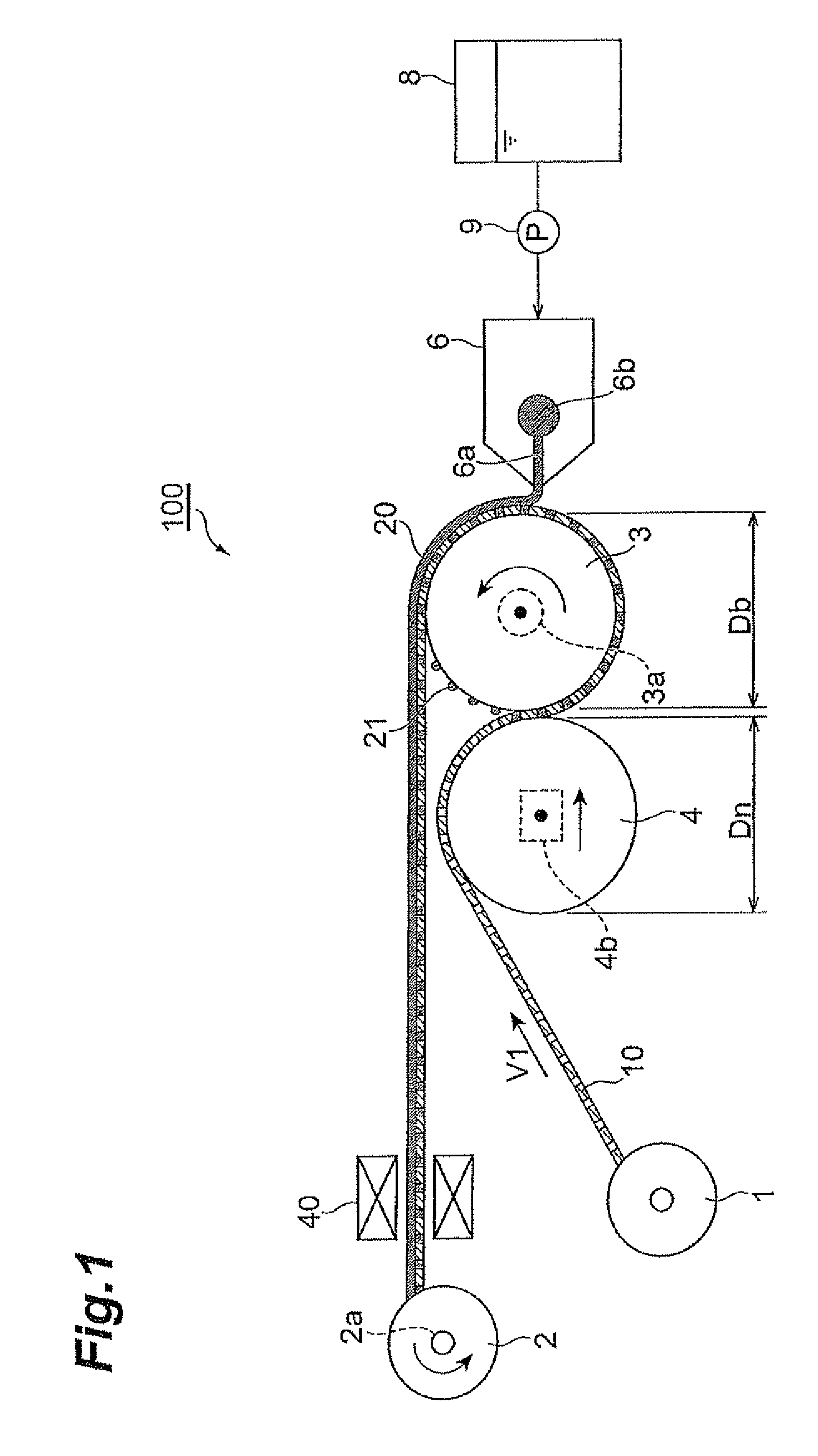
[0042]Using a backup roll having a diameter Db of 120.0 mm, a nip roll having a diameter Dn of 120.0 mm, and a slit die having a slit width of 300 μm, a coating liquid was applied to a surface of a punching current collector sheet made of Al having a thickness of 20 μm and a width of 150 mm and including through holes, each having a diameter of 200 μm, arranged in a zigzag alignment with a center pitch of 200 μm. Here, the coating liquid was prepared by dispersing 50 parts by weight of a powder in which the mass ratio of the active material (LiCo0.33Ni0.33Mn0.34O) / binder (PVdF) / conductive auxiliary (acetylene black) was 80:10:10 into 50 parts by weight of N-methyl-2-pyrollidone acting as a solvent. The viscosity was 270 P. The line speed V1 of the current collector sheet 10 was 1.00 m / min, while the linear speed Vb of the backup roll 3 was 1.10 m / min. The coating liquid was supplied such that the liquid film attained a thickness of 120 μm. The planarity of the electrode after drying...


PUM

PropertyMeasurementUnit
viscosityaaaaaaaaaa
speedaaaaaaaaaa
speedaaaaaaaaaa

Abstract

An electrode manufacturing apparatus comprises a conveying section for conveying a current collector sheet having a plurality of through holes; a backup roll for guiding the conveyed current collector sheet; an applicator for supplying a coating liquid to the current collector sheet on the backup roll; and a nip roll for pressing a part of the current collector sheet where the coating liquid is not supplied yet from the applicator against the backup roll.

Description

BACKGROUND OF THE INVENTION[0001]1. Field of the Invention[0002]The present invention relates to an electrode manufacturing apparatus and an electrode manufacturing method.[0003]2. Related Background Art[0004]An electrode has been known in which a plurality of through holes are formed in a current collector in order to enhance the mobility of electrolyte ions and electrolytic solutions (see, for example, Japanese Patent Application Laid-Open No. 11-111272). For manufacturing such an electrode, a coating liquid for forming an electrode is required to be applied onto a current collector sheet having a plurality of through holes.[0005]As an example of methods for applying a coating liquid onto a current collector sheet, it has been known to supply a coating liquid to the current collector sheet guided on a backup roll as disclosed in the Patent Literature.SUMMARY OF THE INVENTION[0006]When applied to the current collector sheet having a plurality of through holes, however, the coating ...

Claims


Application Information

Patent Timeline
Patent Type & Authority Patents(United States)
IPC IPC(8): H01M4/02H01M4/64H01M4/04H01M4/13H01M4/70H01M4/131
CPCH01M4/0404H01M4/0409Y10T29/49108Y10T29/53135Y10T29/49115Y10T29/10Y02E60/10
Inventor EMOTO, KAZUTOSHINAOI, KATSUOHINOKI, KIYONORIHIRANO, MASAYOSHI
Owner TDK CORPARATION
Why Eureka
Eureka Blog
Learn More