Charged particle beam masking for laser ablation micromachining

a laser ablation and micromachining technology, applied in the field of fabrication microstructures, can solve the problems of poor process resolution, difficult consistent process repeatability, and limited material photochemical etching, and achieve the effect of higher mask resolution and higher resolution processing of samples

Active Publication Date: 2012-05-01
FEI CO
View PDF22 Cites 23 Cited by
  • Summary
  • Abstract
  • Description
  • Claims
  • Application Information

AI Technical Summary

Benefits of technology

[0010]A preferred embodiment includes providing a mask through which a sample is exposed to a laser beam. The mask is fabricated through processes that provide a higher mask resolution than is typically achievable through conventional laser beam processing, thereby allowing for higher resolution processing of the sample than would be possible by laser processing without the mask.

Problems solved by technology

The heat tends to diffuse to an area larger than the laser beam spot, making the resolution of the process poorer than the laser spot size.
Photochemical etching is limited to materials that are photochemically active.
Because electrons are much lighter than ions, electron beams are typically limited to removing material by inducing a chemical reaction between an etchant vapor and the substrate.
5856-5861 (2004) (“Joglekar et al.”) shows that features smaller than the wavelength can be achieved using laser pulses shorter than about 10 picoseconds near the critical intensity for ablation The impact of small deviations in pulse energy on the resulting feature makes this process difficult to repeat consistently.
While a charged particle beam typically has greater resolution than a laser beam and can micromachine an extremely small structure, the beam current is limited and the micromachining operation can be unacceptably slow.
Laser micromachining, on the other hand, is generally much faster, but the resolution is inherently limited by the longer beam wavelength.
A problem with sequential processing is determining when to stop the faster, less precise laser micromachining and to begin the more precise charged particle beam processing.
If the laser processing is stopped too late, the work piece will be damaged.
Determining when to stop processing is referred to as “endpointing.” While there are several known methods for detecting when a micromachining process cuts through a first material to expose a second material, it is typical to stop laser processing before a change in material is reached, and so determining the end point is more difficult.
While sequential processing—laser processing a sample followed by particle beam processing—has its advantages, there remain problems of the endpointing and of the relatively low resolution of the original laser processing.

Method used


Image

  • Charged particle beam masking for laser ablation micromachining
  • Charged particle beam masking for laser ablation micromachining
  • Charged particle beam masking for laser ablation micromachining

Examples


Embodiment Construction

[0021]Although those of ordinary skill in the art will readily recognize many alternative embodiments, especially in light of the illustrations provided herein, this detailed description is exemplary of the preferred embodiments of the present invention, the scope of which is limited only by the appended claims.

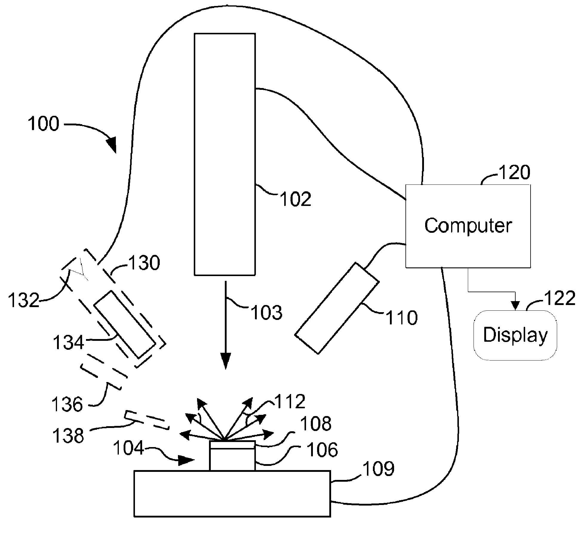
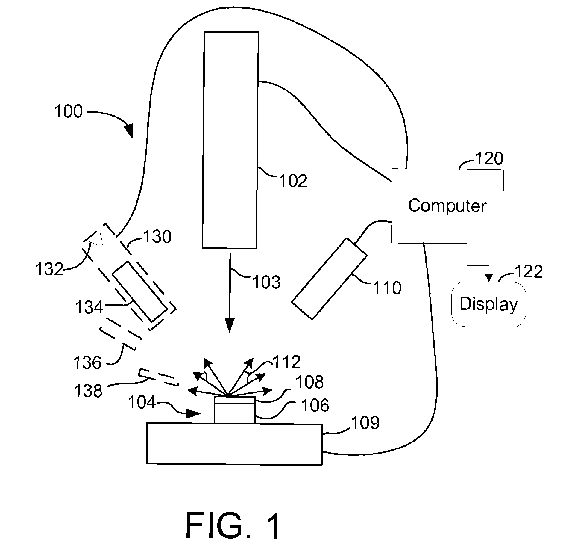
[0022]Preferred embodiments of the present invention fabricate a high resolution mask through a process such as charged particle beam processing. The work piece is subsequently exposed to a laser beam through the mask, the mask blocking or restricting portions of the work piece to the laser beam exposure. The mask is preferably fabricated directly on the work piece surface. The terms “work piece,”“sample,” and “specimen” are used interchangeably in this application.

[0023]In one preferred embodiment, the mask is deposited directly onto the work piece surface using charged particle beam-induced deposition. An ultra short laser pulse is then directed toward the work piece surfac...


PUM

PropertyMeasurementUnit
diameteraaaaaaaaaa
diameteraaaaaaaaaa
energyaaaaaaaaaa

Abstract

An improved method for substrate micromachining. Preferred embodiments of the present invention provide improved methods for the utilization of charged particle beam masking and laser ablation. A combination of the advantages of charged particle beam mask fabrication and ultra short pulse laser ablation are used to significantly reduce substrate processing time and improve lateral resolution and aspect ratio of features machined by laser ablation to preferably smaller than the diffraction limit of the machining laser.

Description

TECHNICAL FIELD OF THE INVENTION[0001]The present invention relates generally to fabricating microstructures, and more particularly, to laser micromachining.BACKGROUND OF THE INVENTION[0002]Removing material from a substrate to form microscopic or nanoscopic structures is referred to as micromachining, milling, or etching. Lasers beams and charged particle beams are two particular technologies used for micromachining. Each has advantages and limitations in various applications.[0003]Laser systems use several different mechanisms for micromachining. In some processes, the laser is used to supply heat to a substrate to induce a chemical reaction. The reaction occurs only in the heated areas. The heat tends to diffuse to an area larger than the laser beam spot, making the resolution of the process poorer than the laser spot size. Another mechanism used in laser micromachining is photochemical etching, in which the laser energy is absorbed by individual atoms or molecules of the substra...

Claims


Application Information

Patent Timeline
Patent Type & Authority Patents(United States)
IPC IPC(8): G21G5/00
CPCB23K26/0635B23K26/0661B23K26/18G03F7/70383B23K2201/40B23K2201/42B23K26/0624H01J37/228H01J2237/31749B23K2101/40B23K2101/42G21G5/00
Inventor STRAW, MARCUSTOTH, MILOSRANDOLPH, STEVENLYSAGHT, MICHAELUTLAUT, MARK
Owner FEI CO
Why Eureka
Try Eureka