Virtual group maintenance and security

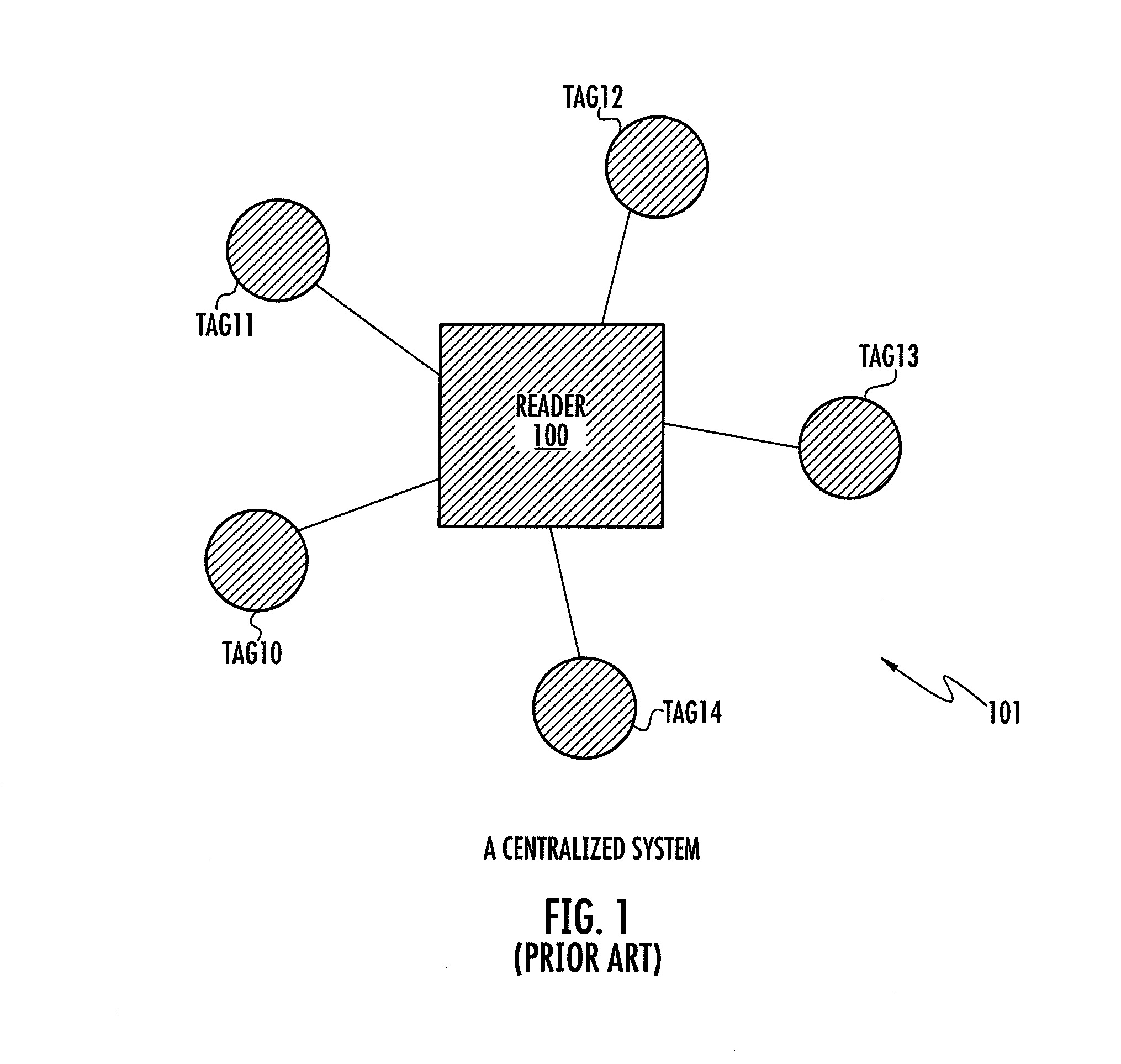
a virtual group and monitoring technology, applied in the direction of burglar alarm mechanical actuation, instruments, electric signalling details, etc., can solve the problems of increasing the implementation cost by tenfold, inaccuracy of the range threshold in which the alarm is triggered, and the cost of a relatively expensive monitor (e.g. rfid reader b>100/b>), so as to save battery power

Active Publication Date: 2012-05-01
ZEBRA TECH CORP
View PDF11 Cites 41 Cited by
  • Summary
  • Abstract
  • Description
  • Claims
  • Application Information

AI Technical Summary

Benefits of technology

[0013]The intercommunication between the tags of the group includes using unicast ultra-wide band transmitted messages and receiving unicast response messages to relay information regarding completeness of the group between the tags of the group, The intercommunication is preferably performed during a time interval, the time interval is sufficiently long so that the first tag of the group to interrogate receives an interrogation signal from the last of the group to interrogate and outside the time interval all the tags switch into a sleep mode, thereby conserving battery power.

Problems solved by technology

In may applications the cost of a relatively expensive monitor (e.g. RFID reader 100), is typically more than hundred times the cost of an RFID tag.
If a group of tagged devices includes about ten elements, the inclusion of monitor 100 increases the cost of implementation by tenfold.
A further limitation of prior art system 101 and other systems, is the inaccuracy of the range threshold in which the alarm is triggered.
In the absence of an accurate distance measurement, system 10 may either trigger an alarm when the tagged devices are still close to each other, or too late, when one of tags 10-14 has been removed without prior authorization and the security breach is not prevented.
In fact, prior art systems typically do not perform any distance determination measurement but rather than rely on attenuation of the RP signals which results in range varying by an order of magnitude because of differences in RF attenuation, reflections and multipath interference throughout the RF propagation pats between monitor 100 and tags 10-14.
The lack of accurate range determination creates an increased potential for security breaches in prior art systems 10.
Contactless smart card technology is vulnerable to relay attacks: An attacker can trick the reader into communicating with a victim smart card that is very far away.
The attack using a ghost and leech on a contactless smart card can be made very difficult if an accurate distance determination measurement is performed to the contactless smart card.

Method used


Image

  • Virtual group maintenance and security
  • Virtual group maintenance and security
  • Virtual group maintenance and security

Examples


embodiment 201

[0039]An implementation of embodiments of the present invention based on ultra-wide band signaling of active RFID tags, preferably includes the following main characteristics: Each tag can receive and transmit ultra-wide band signals. A tag can communicate with another tag and preferably all other tags in the group. In an efficient protocol each transmitting tag sends a broadcast message, to which all other tags respond, and the originating tag gets immediate information regarding all other tags in the group. This however requires a sophisticated tag receiver processing. In another protocol, each tag transmits a unicast message and receives a response from only one other tag, which in turn is responsible for communicating with the next tag, and so on. For instance in embodiment 201, tag 24 is queried by tag 23, tag 23 is queried by tag 22, tag 22 is queried by tag 21, tag 21 is queried by tag 20 and tag 20 is queried by tag 24. In another protocol, each tag (in his turn) queries eac...

embodiment 200

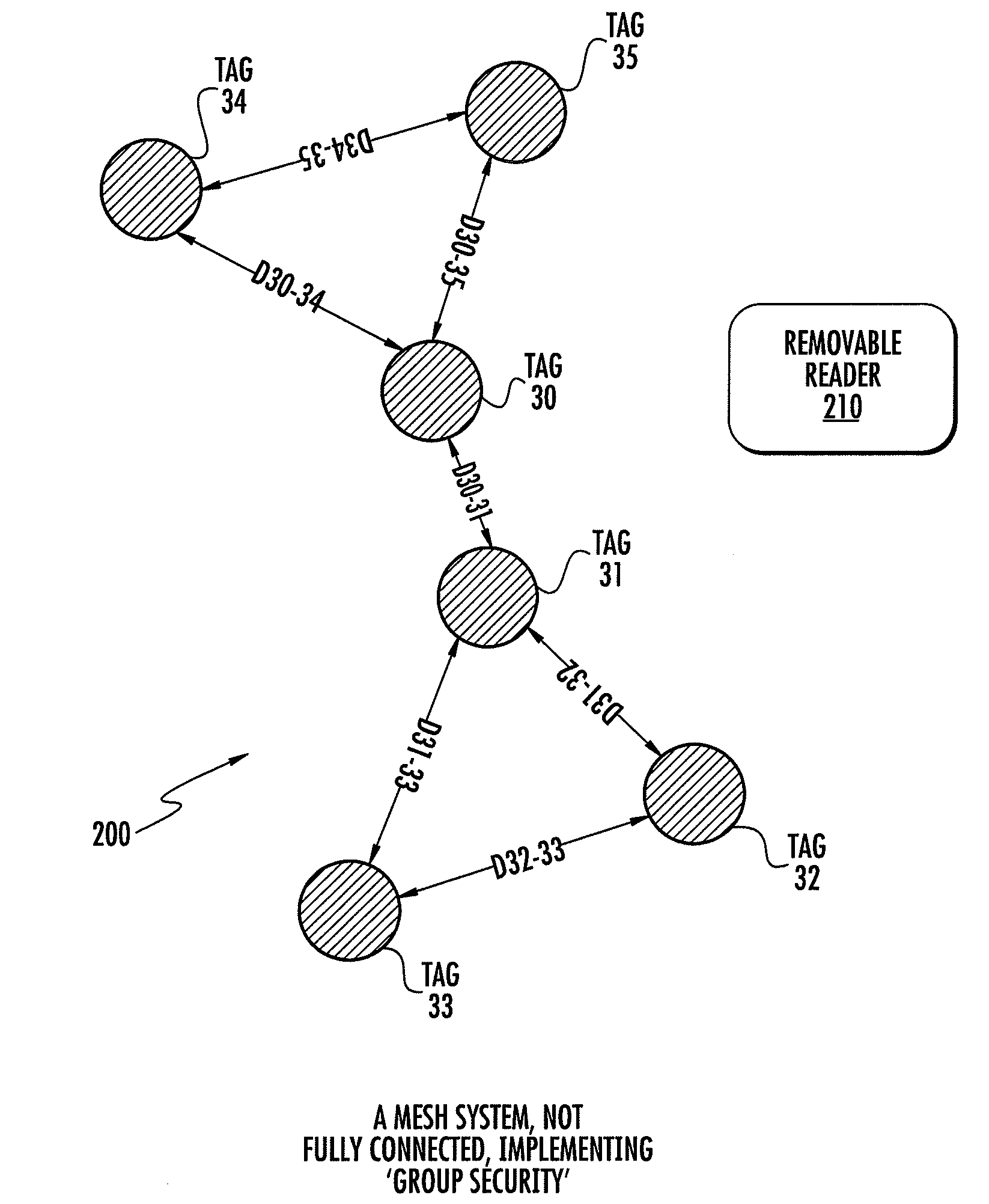
[0049]Reference is now also made to FIG. 4, which illustrates an alarm system attached to one or more of the tags. The connection to the alarm system may be wired as in alarm 401 or wireless to wireless alarm system 402. In a preprogrammed schedule, each tag of the group interrogates the other tags of the group using either unicast, multicast or broadcast command, and tests each for presence and for being in a preprogrammed authorized range. In embodiment 200, (FIG. 2a) each tag measures the round-trip delay to four other tags preferably using ultra-wide band signaling according to the teachings of WO2003 / 098528. If maximum range is violated, an alarm state is reached. The alarm is communicated to the external world using sound, light, or if there is reader 210 in the area, using an alarm message or interrupt. Alternatively, if there is no reader 210 an alarm is generated using an alarm system 401, 402. In an alternative embodiment, a device e.g. cellular telephone connected to one ...


PUM


Abstract

A method of providing security and maintenance of a group of devices using a group of tags. Each of the tags is attached to a device and includes a radio frequency transceiver for intercommunicating using ultra-wide band signals. Using the intercommunication, distance between two of the tags is determined and an alarm is triggered when the distance is greater than a previously defined threshold distance. The distance is preferably determined by measuring a round trip delay time between the transmission of a transmitted signal to the other tag and reception of a response signal in response to the transmitted signal from the other tag. The distance is preferably determined by measuring a time delay between transmitting a unicast ultra-wide band message and receiving a unicast response message. The intercommunication preferably uses ultra-wide band signals which relay information regarding completeness of the group between the tags of the group. A configuration mechanism is typically used for configuring the group. Upon completing the configuration, the configuration mechanism, e.g. reader or monitor, may be removed and the tags maintain the group and provide security by the intercommunication between the tags. The tags are preferably synchronized to transmit and receive solely during a previously determined periodic sequence of time intervals.

Description

FIELD OF THE INVENTION[0001]The present invention relates to asset management using a radio frequency identification system and in particular the present invention includes active RFID tags which have a security function without the presence of an active reader in the vicinity of the RFID tags. The most preferred implementations use ultra-wide band active RFID tags.BACKGROUND OF THE INVENTION[0002]Reference is made to FIG. 1 a prior art system 101 for securing a group of elements or devices. Five RFID tags 10-14 are each attached to one of the devices. A monitor 100, a central controller of the system, monitors tags 10-14 by communicating with each of tags 10-14. The term “reader” is also used herein interchangeably to refer to a central controller or monitor 100. Prior art system 101 of FIG. 1 can be described as centralized. Monitor e.g. an RFID reader 100, monitors one or more RFID tags 10,11,12,13,14. Monitor 100 typically functions differently from tags 10-14. The main function...

Claims


Application Information

Patent Timeline
Patent Type & Authority Patents(United States)
IPC IPC(8): G08B21/00
CPCG08B21/0227G08B21/0238H04L67/12H04L63/104H04L63/0492
Inventor KAPLAN, GIDEONMENKES, AVRAHAMRAPHAELI, DAN
Owner ZEBRA TECH CORP
Why Eureka
Try Eureka