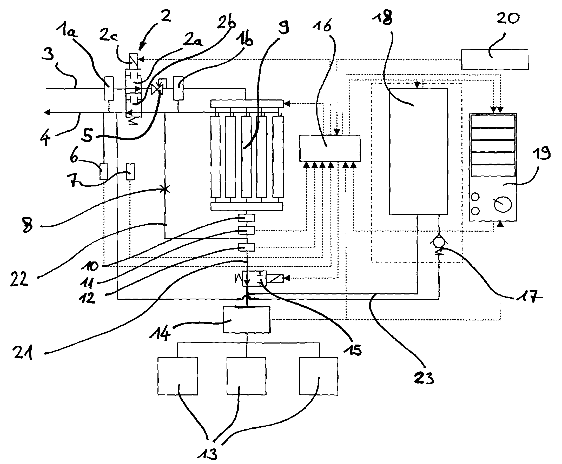
[0011]Still further, the shut off valve may preferably comprise a first valve unit adapted to interrupt the flow through the bleed air supply line and a second valve unit adapted to interrupt flow through a vent line connecting the filter unit with
ambient pressure, wherein the first valve unit is adapted to be switched between a first condition wherein the flow through the bleed air supply line and the flow through the vent line is open and a second position wherein the flow through the bleed air supply line and the flow through the vent line is shut. With this embodiment it is possible to pneumatically seal the whole oxygen breathing device. This will further extend the lifetime of the filter unit as it is neither in flow communication with the bleed
air line and the vent line nor under bleed air pressure in times of non-use which may be achieved by additional valve means or a short time
delay between closing of the two valve units.
[0012]According to a still further preferred embodiment, a
pressure sensor and an
oxygen sensor is comprised in the oxygen breathing device, wherein the
pressure sensor and the
oxygen sensor are arranged in the oxygen supply line and the
control unit is adapted to monitor the signals of the
pressure sensor and the
oxygen sensor and to provide an output
signal indicating
proper function of the oxygen breathing device, in particular to provide such output
signal after a certain predetermined time period has elapsed after the pressure sensor
signal had reached a predetermined limit and the oxygen sensor signal has reached a predetermined limit. This preferred embodiment is particularly helpful for monitoring proper functioning of the breathing device after switching on. The absolute content of oxygen in the breathing air depends on the concentration of oxygen in the breathing air and the pressure of the breathing air. Thus, a reliant determination of the
oxygen content is only possible if a certain
pressure level is achieved and maintained or permanently monitored. To provide such reliant
oxygen content measurement, the pressure of the breathing air is monitored in the oxygen supply line and if this
pressure level has reached or exceeded a certain predetermined level, a short time
delay starts and after this time
delay has elapsed the oxygen concentration is measured via the oxygen sensor. By this, the
oxygen content in the oxygen supply line can be determined in a safe manner since pressure is likely to be constant during
oxygen measurement. It is to be understood, that both sensors are arranged in flow direction behind the filter unit. Preferably, the pressure sensor is arranged in flow direction behind the oxygen sensor.
[0015]While it was formerly known to provide a water separator in front of the first pressure
regulator to prevent introduction of
liquid water into the whole
system at the bleed air inlet of the whole oxygen
breathing system, according to this preferred embodiment, two water separators are provided whereby the first is arranged before the pressure
regulator and the second is provided behind the pressure
regulator. By this, a significant amount of
free water in the bleed air can be extracted by the first water separator. Additional water which is precipitated after temperature decrease in the pressure regulator is extracted in the second water separator. Although this water usually is not present in the air provided to the user because in the course of further
processing of the bleed air in the
system this water is stored in hygroscopical parts of the filter unit and is volatilized following temperature increase, the second water separator significantly extends the maintenance period or the time of the need for replacement of the filter unit since the enrichment of the hygroscopical
sieve beds within the filter unit with water significantly reduces the lifetime of the filter unit.
[0016]According to a further preferred embodiment, the oxygen breathing device is further improved by comprising an oxygen sensor monitoring the oxygen flow to the connection port of the oxygen breathing device, the oxygen sensor being connected to the
control unit, wherein the control unit is adapted to compare the oxygen sensor signal to a predetermined desired minimum
oxygen level and to activate the
starter of the chemical oxygen generator if the oxygen flow falls below said level. It is to be understood that this oxygen sensor can be the same oxygen sensor as described above for other preferred embodiments or can be an independent oxygen sensor. The provision of such oxygen sensor connected to the control unit allows a permanent monitoring of the oxygen flow and an activation of the auxiliary oxygen supply
system in case that the signal of the oxygen sensor signalizes that the oxygen flow has fallen below a predetermined minimum level. By this, an automatic activation of the chemical oxygen generator can be produced to prevent an interruption of the oxygen supply to the user in the course of failure of the main oxygen supply system. In particular, said control unit can start the
chemical reaction within the chemical oxygen generator via the
starter and may additionally switch an oxygen source select valve a certain time period after said start to allow for sufficient oxygen generation within the chemical oxygen generator. In most cases of failure of an oxygen supply system based on bleed air and a filter unit the oxygen flow will not fall under a predetermined level in a sudden change but will rather slowly fall below the predetermined level. In such cases, it is not required to immediately switch to an alternative oxygen supply system but the oxygen flow via the main system can be maintained for a certain period of time after the decrease of oxygen flow was detected.
[0017]According to a still further preferred embodiment, at least one
oxygen mask and a box for storing said
oxygen mask is provided, wherein a switch is arranged at the box, the switch being coupled to a control unit to activate oxygen supply if the
oxygen mask is taken out of the box. By this, it is possible to store the oxygen
mask in a non-use situation in a box where it is to be understood that the box could include a hook, a frame or the like adapted to take up the oxygen mask in a hanging or
lying position. In case that the oxygen mask is stored in said box, a switch is provided in that box which is arranged such that it is activated as soon as the oxygen mask is stored in the box. By this, the switch coupled to said control unit can deactivate oxygen flow as soon as the oxygen mask is put into the box and the control unit can activate the oxygen flow as soon as the mask is taken out of the box.

