Apparatus and method for opening/closing lid of closed container, gas replacement apparatus using same, and load port apparatus

a technology for opening/closing lids and closed containers, which is applied in the directions of liquid handling, packaging goods, transportation and packaging, etc. it can solve the problems of oxidizing the surface of the wafer or the surface of the layer formed on the wafer during the storage of the wafer, reducing the pressure in the interior of the pod in which the wafers are enclosed, and degrading from a preferred condition of the enclosure, so as to reduce the possibility of dust entering the interior of the pod, the effect of enhancing

Active Publication Date: 2012-05-08
TDK CORPARATION
View PDF19 Cites 14 Cited by
  • Summary
  • Abstract
  • Description
  • Claims
  • Application Information

AI Technical Summary

Benefits of technology

[0013]The present invention has been made in view of the above described background, and has as an object to provide a gas replacement apparatus that can replace the gas in the interior of the pod quickly and efficiently. It is also an object of the present invention to provide a gas replacement apparatus that enables a reduction in the possibility of entrance of dust or the like generated from a pod and peripheral movable elements in gas replacement operations into the interior of the pod, which will have to be taken care of in order to enhance the production efficiency with an increase in the wafer diameter in the future. It is a further object of the present invention to provide an apparatus and method for opening and closing a lid of a closed container or pod that can be used in such a gas replacement apparatus, and a load port apparatus using such an opening and closing apparatus.
[0015]To achieve one of the above objects, according to another aspect of the present invention, there is provided a gas replacement apparatus comprising the above described lid opening and closing apparatus, a cabinet that constitutes a chamber with walls including the outer wall, a door drive mechanism that is disposed outside the chamber and can move the door toward and away from the lid, a bellows that spatially separates a joining portion of the door drive mechanism and the door from the chamber, a latch member drive mechanism that is connected to the latch mechanism drive member and drives the latch mechanism drive member, a gas nozzle that can supply inert gas into the interior of the chamber, and an exhaust port through which surplus of the inert gas supplied into the chamber is exhausted, the exhaust port being capable of maintaining the pressure in the interior of the chamber at a level higher than the pressure outside the chamber.
[0017]According to the present invention, replacement of the gas in the interior of a pod can be performed through the opening of the pod. The present invention enables quick and effective gas replacement. According to the present invention, purging can be performed in a state in which the interior of a purge chamber (i.e. a chamber used for purging) is kept at a pressure a little higher than the atmospheric pressure, and therefore the gas replacement apparatus can be constructed by providing only a space needed to open and close the lid. Thus, the volume of the interior space of the chamber serving as a closed space used in gas replacement can be minimized, and therefore the quantity of inert gas needed in the replacement process can be made smaller.
[0018]According to the present invention, the elements of the pod that are brought into the chamber may be only the lid. Therefore, the elements brought into the chamber that have been stored in an environment in which the degree of cleanness is lower than that in the interior of the chamber and the pod can be made minimum. Thus, contamination of wafers or the like with contaminants associate with such elements can be reduced as much as possible. In connection with this, entrance of dust generated from a movable portion of such an element into the chamber can be prevented from occurring by providing a seal to separate the movable portion from the interior space of the chamber. Furthermore, by preventing ambient air from entering into the chamber through an apparatus for opening and closing the lid, the degree of purity of the inert gas in the interior of the chamber can be kept at a higher level. In addition, since while purging is performed, a significantly large area of the lid of the pod that has been exposed to the ambient air while storage is prevented from being exposed to the clean space formed during the purging. Therefore, scattering of contaminants in the chamber from the surface of the lid can be prevented.

Problems solved by technology

In recent years, with decreases in the size of semiconductor devices and with enhancements of their performance, oxidization of the surface of the wafer or the surface of layers formed on the wafer by oxidizing atmosphere during wafer storage has become a problem.
However, it is well known that the pressure in the interior of the pod in which the wafers are enclosed decreases with time, and the enclosure condition is degraded from a preferred condition with time.
However, there is a possibility that the following problem is encountered or will be encountered in the future by the above described prior art methods when they are put into practice.
Specifically, in the case of the method disclosed in Japanese Patent Application Laid-Open No. 2004-235516, it is difficult to achieve sealing of the above-mentioned so-called mini environment since a drive system for means for holding the lid of the pod is provided.
Therefore, the degree of purity of the inert gas supplied into the interior of the pod is hard to be enhanced beyond a certain level.
Furthermore, there are many driving elements in the mini environment, and dust generated from such elements will be stirred up by down-flow produced in the mini environment.
Therefore, there is a possibility that such dust enters into the pod.
But use of this countermeasure leads to an unduly large increase in the amount of inert gas used, which will be a problem in terms of semiconductor manufacturing cost.
However, in practice, since the direction of flow of the supplied and discharged inert gas is perpendicular to the planes in which the wafers stored in the pod extend, the gas replacement efficiency is low in the regions between the wafers, and there is a possibility that the gas cannot be replaced effectively even if purging is performed over a significantly long period of time.
Furthermore, this problem can be more serious with an increase in the wafer diameter in recent years.
Thus, this method is disadvantageous in that the structure of the apparatus is complex and the size thereof is large.
Thus, when the pod is brought into the chamber, the environment in the chamber can be contaminated with the extraneous matters.
However, this necessarily requires time for the gas replacement operation, and there arises a problem of elongation of the processing time.
This problem can be more serious with an increase in the pod size necessitated by an increase in the wafer diameter in recent years.

Method used


Image

  • Apparatus and method for opening/closing lid of closed container, gas replacement apparatus using same, and load port apparatus
  • Apparatus and method for opening/closing lid of closed container, gas replacement apparatus using same, and load port apparatus
  • Apparatus and method for opening/closing lid of closed container, gas replacement apparatus using same, and load port apparatus

Examples


Embodiment Construction

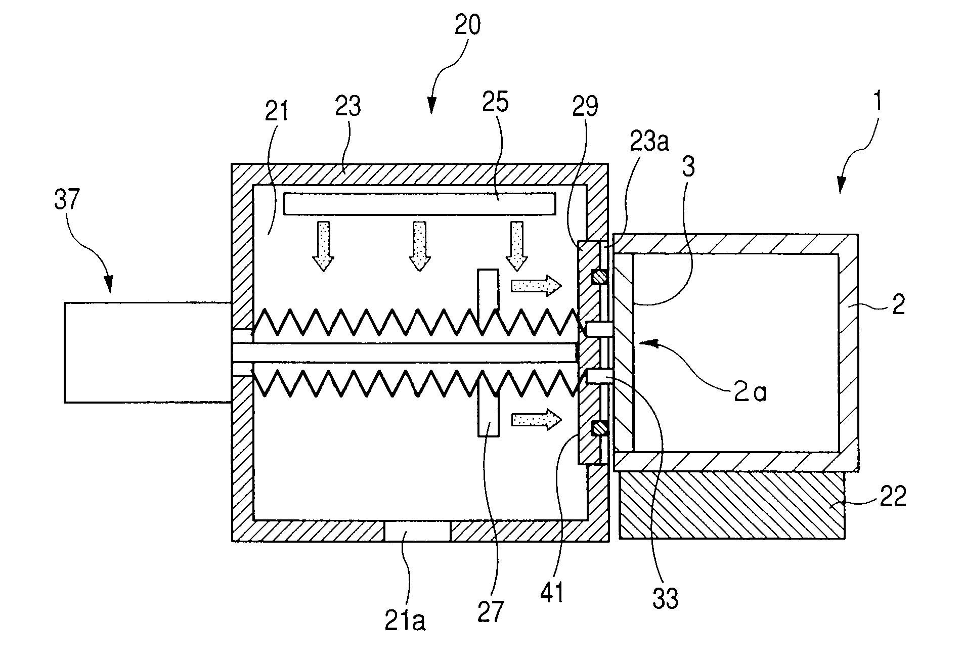
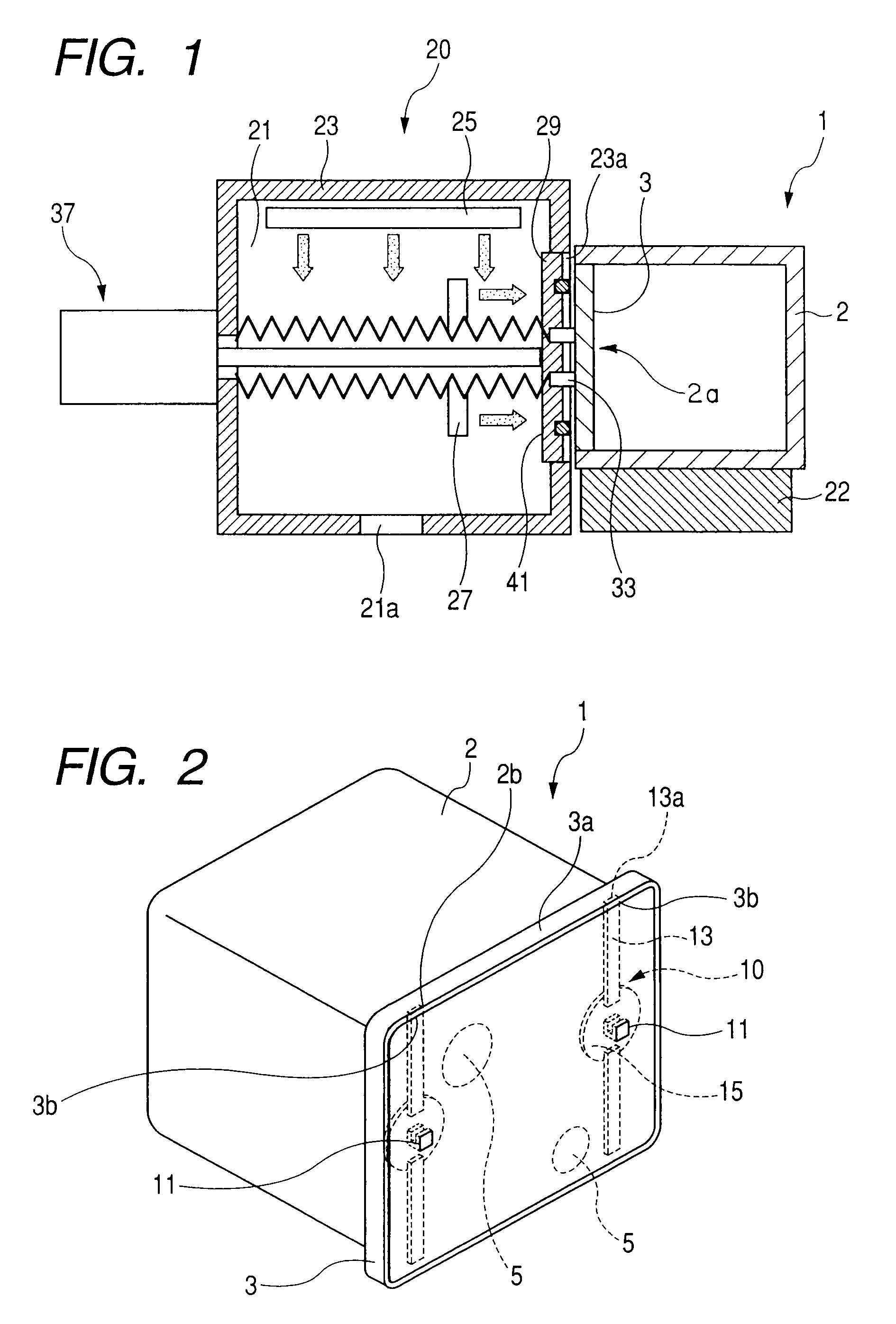
[0036]An embodiment of the present invention will be described in the following with reference to the accompanying drawings. FIG. 1 is a diagram schematically showing a cross section of a gas replacement apparatus equipped with an apparatus for opening and closing the lid of a pod according to the present invention, and a pod loaded on the gas replacement apparatus. The pod 1 shown in FIG. 1 has a substantially cubical main body 2 having an opening 2a on one side thereof and a lid 3 that closes the opening 2a.

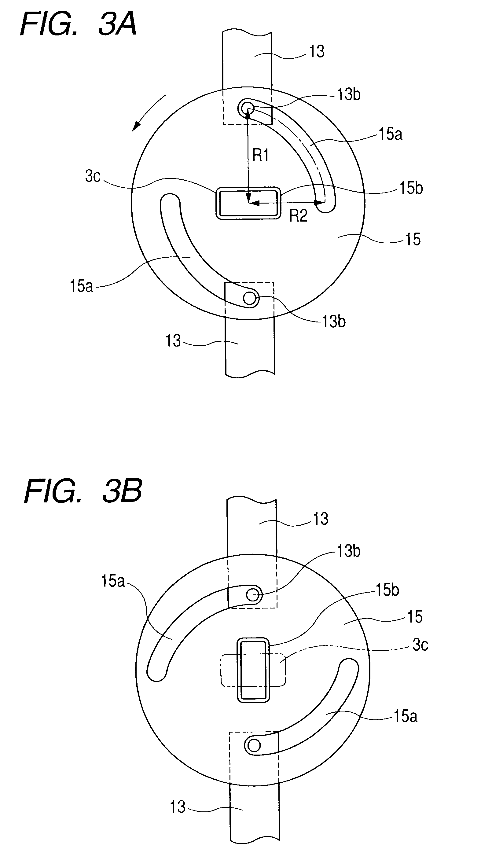
[0037]Here, the structure of the pod 1 that is used with the apparatus according to the present invention will be briefly described with reference to FIGS. 2, 3A, and 3B. FIG. 2 is a schematic perspective view of the pod. FIGS. 3A and 3B are enlarged front views of a latch mechanism, showing a latched state and an unlatched state respectively. The lid 3 has a flat plate-like shape having an outer side surface (the surface to be opposed to the lid opening and closing apparatus)...


PUM

PropertyMeasurementUnit
pressureaaaaaaaaaa
sizeaaaaaaaaaa
degree of purityaaaaaaaaaa

Abstract

The invention provides a purge apparatus that purges the gas in the interior of a FOUP with a high purging efficiency and an apparatus for opening / closing the lid of a FOUP for use in the purge apparatus. The purge apparatus has a cabinet having an opening portion through with the lid of the FOUP can pass, a door that can close the opening portion and hold the lid, and a gas supply nozzle provide in the cabinet. In this apparatus, a seal member is provided in such a way as to surround an element that is provided on the surface of the door and adapted to actuate a latch mechanism of the lid. The seal member spatially separates the element that is adapted to actuate the latch mechanism from the external space in a state in which the door is holding the lid.

Description

[0001]This application claims priority from Japanese Patent Application No. 2008-082950 filed on Mar. 27, 2008, which is hereby incorporated by reference herein.BACKGROUND OF THE INVENTION[0002]1. Field of the Invention[0003]The present invention relates to an apparatus and a method for opening and closing a lid of a closed container that is used to transport silicon wafers or the like between semiconductor processing apparatuses in a semiconductor manufacturing process etc. More specifically, the closed container is a container in which silicon wafers are stored and that is used to transport the wafers between the semiconductor processing apparatuses, and the present invention relates to an apparatus that opens and closes the lid of the container, a gas replacement apparatus that replaces the gas in the interior of the container, and what is called a FIMS (Front-Opening Interface Mechanical Standard) system or a load port apparatus that detaches the lid from the container to take o...

Claims


Application Information

Patent Timeline
Patent Type & Authority Patents(United States)
IPC IPC(8): H01L21/02
CPCH01L21/67373H01L21/67376H01L21/67393H01L21/67772H01L21/67775Y10S414/139
Inventor OKABE, TSUTOMU
Owner TDK CORPARATION
Why Eureka
Try Eureka