
Message, control and reporting interface for a distributed network access system

a distributed network access system and message control technology, applied in the field of communication networks, can solve the problems of inability to expand or extend the packet processing throughput of the router, the limited range of data services that a service provider can offer in addition to basic packet routing, and the inability to add new services or modify existing services, etc., to achieve the effect of improving scalability, flexibility, extensibility, and security

Active Publication Date: 2012-05-22
VERIZON PATENT & LICENSING INC
View PDF89 Cites 47 Cited by
  • Summary
  • Abstract
  • Description
  • Claims
  • Application Information

AI Technical Summary

Benefits of technology

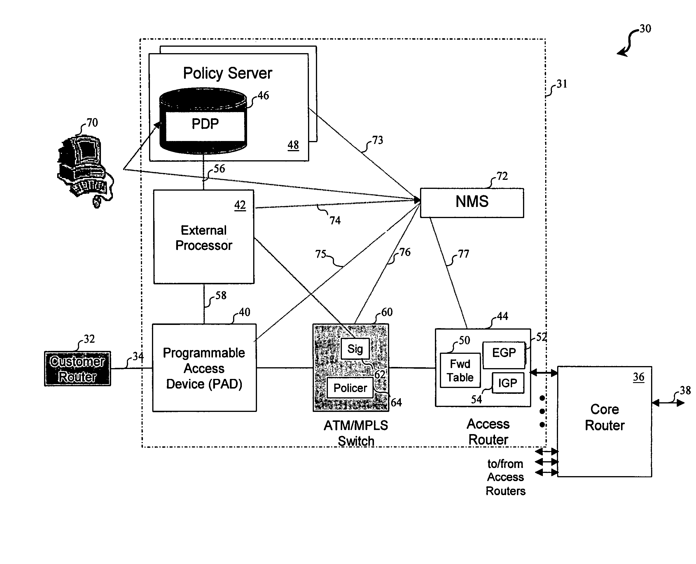
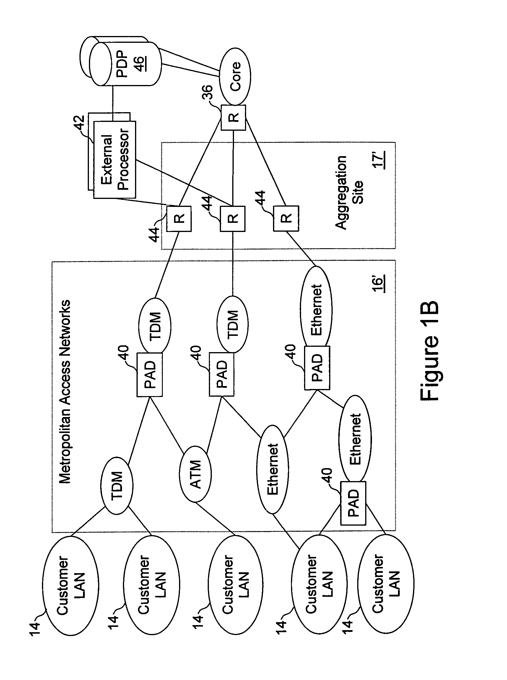
[0019]Thus, in accordance with the present invention, conventional monolithic, proprietary edge routers are replaced with a distributed network access system that allocates the functionality of traditional edge routers (as well as additional functionality) among three logical modules: a programmable access device, an external processor, and an access router. According to a preferred embodiment of the present invention, basic routing of packets between input and output ports of the access network is performed by the access router. However, forwarding and generic traffic conditioning functions, such as marking, policing, monitoring, shaping, and filtering, are implemented in the programmable access device, and service functions, such as message interpretation, signaling, admission control, and policy invocation, are implemented in the external processor. As detailed infra, this distribution of functionality results in numerous advantages, including improved scalability, flexibility, extensibility, interoperability, security, and service provisioning.

Problems solved by technology

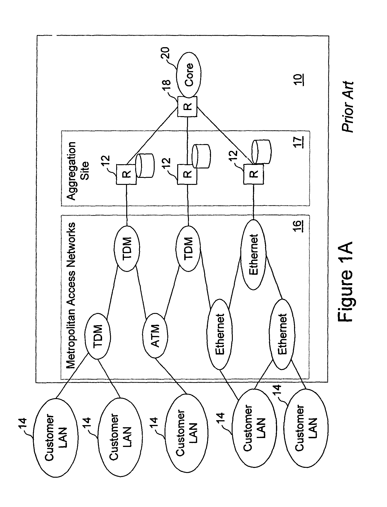
The state of the art in router design to a large extent dictates the network design shown in FIG. 1A because routers are expensive and must operate on highly aggregated traffic flows.
Consequently, the range of data services that a service provider can offer in addition to basic packet routing is limited by the control software offered by router vendors.
In addition, the packet-processing throughput of a router is generally limited by its originally installed processing hardware and cannot be expanded or extended without replacement of the entire router.
First, because routers traditionally have a single controller providing all services for all message types, edge router controllers tend to be quite complex, making it difficult and expensive to add new services or modify existing services.
Second, conventional monolithic router architectures are not readily scalable, which presents a significant problem for service providers, particularly in light of the phenomenal growth of Internet traffic.
Consequently, the processing capabilities of deployed routers cannot easily be scaled to keep pace with increasing traffic.
Third, conventional monolithic router designs also have limited flexibility and extensibility.
However, conventional edge routers are not capable of classifying a wide variety of traffic types while enforcing policy controls or of responding to dynamic requests for capacity, and this functionality is difficult to incorporate within currently deployed monolithic edge routers.
Fourth, because of the proprietary nature of router architectures and services, if a service provider deploys routers from multiple vendors in a communication network, the proprietary services implemented by the different router vendors will not necessarily inter-operate.
Consequently, service providers are not able to purchase routers and switches from one vendor and purchase service control software from another vendor.
Furthermore, a service provider cannot offer its communication network as a platform for a wholesale provider to offer value-added data services utilizing the existing base network capabilities.

Method used


Image

  • Message, control and reporting interface for a distributed network access system
  • Message, control and reporting interface for a distributed network access system
  • Message, control and reporting interface for a distributed network access system

Examples


Embodiment Construction

Distributed Network Access System Architecture

[0053]With reference again to the figures and in particular with reference to FIG. 2, there is depicted a high-level block diagram of a portion of a communication network 30 having a distributed network access system 31 in accordance with the present invention. As illustrated, communication network 30 may be coupled to equipment of a number of customers (one of which is represented by a customer router 32) by an access line 34. As in FIG. 1, access line 34 may employ any of a number of commonly utilized transport network technologies, such as Ethernet, SONET, ATM and frame relay, and may further include unillustrated aggregation hardware.

[0054]As with conventional networks, communication network 30 includes one or more core communication links 38 (e.g., trunk lines) coupled to one or more core routers 36. However, in contrast to conventional communication networks, such as that illustrated in FIG. 1, customer router 32 does not interface...


PUM


Abstract

In a network access system including an external processor and a programmable access device, the external processor transmits a control message to the programmable access device to establish a configuration of the programmable access device. The programmable access device then communicates messages to the external processor for service processing in accordance with the configuration. For example, the control message may be a filter control message that establishes a configuration of a packet header filter in the programmable access device. The packet header filter then communicates network messages filtered from a packet flow in accordance with the configuration established by the control message. To limit the communication of network messages from the programmable access device to the external processor, the external processor can send a message setting message interface flags in the programmable access device. The external processor may also transmit a monitor control message to the programmable access device to establish a configuration of a monitor in the programmable access device. The programmable access device then communicates reporting messages to the external processor in response to the configuration of the monitor.

Description

CROSS-REFERENCE TO RELATED APPLICATIONS[0001]The present application is related to the following applications, which are filed on even date herewith and incorporated herein by reference:[0002](1) U.S. patent application Ser. No. 09 / 723,482 entitled “Network Access System Including a Programmable Access Device Having Distributed Service Control;” now U.S. Pat. No. 7,046,680, issued Apr. 26, 2006;[0003](2) U.S. patent application Ser. No. 09 / 723,481, entitled “Programmable Access Device for a Distributed Network Access System;” and[0004](3) U.S. patent application Ser. No. 09 / 723,501, entitled “External Processor for a Distributed Network Access System.”BACKGROUND OF THE INVENTION[0005]1. Technical Field[0006]The present invention relates in general to communication networks and, in particular, to an IP-centric communication network. Still more particularly, the present invention relates to an IP-based communication network including a network access system having distributed and sepa...

Claims


Application Information

Patent Timeline
IPC IPC(8): G06F15/173H04L12/56H04L12/24H04L12/26H04L29/06
CPCH04L12/2602H04L29/06H04L41/0893H04L43/00H04L69/164H04L69/165H04L41/0663H04L43/06H04L43/16H04L69/16H04L69/22H04L41/0894H04L9/40
Inventor MCDYSAN, DAVETHOMAS, HOWARD LEEYAO, LEI
Owner VERIZON PATENT & LICENSING INC
Learn More