Image null-balance system with multisector-cell direction sensing

a null-balance system and multi-sector technology, applied in the direction of distance measurement, instruments, surveying and navigation, etc., can solve the problems of manned and unmanned apparatuses, system response is relatively slow, and the line-of-sight measurement is relatively inaccurate, so as to facilitate the discrimination of plural and even multiple incident light beams.

Active Publication Date: 2012-06-19
ARETE ASSOCIATES INC
View PDF5 Cites 8 Cited by
  • Summary
  • Abstract
  • Description
  • Claims
  • Application Information

AI Technical Summary

Benefits of technology

[0062]In particular, the nested field of view within the larger field of regard facilitates discrimination of plural and even multiple incident light beams from one another.
[0063]This two-field characteristic also makes it easier for the invention to continue monitoring of one beam while also continuing to watch for others. Moreover it enables an artificially generated light beam, to be detected, to be more readily distinguished from natural sources.

Problems solved by technology

The availability of optical systems that dazzle or blind an equipment operator, guide a beam-following vehicle to an equipment platform, or laser-pinpoint an object of interest, represent a threat to manned and unmanned apparatus.
These systems are relatively slow in their response, and relatively inaccurate in terms of their line-of-sight (LOS) measurement of the location of the incoming laser beam.
In addition, they are relatively bulky and heavy.
Further, existing laser-detection and -warning receivers provide little if any spectral information.
They are bulky (not compatible with installation in an aircraft cockpit), highly inaccurate in terms of determining location of a laser-beam source, and yield no spectral information for the incoming beam.
Again, however, these provide no directional or spectral information, and can only detect average irradiance levels as low as 10−11 W / cm2.
Quad cell response is very fast, but the pointing accuracy of such a conventional system is quite poor—particularly in a low-light-level environment.
This is because signal-to-noise properties of such operation are distinctly unfavorable in comparison with those of, e.q., a PSD also as conventionally used.
The mirrors were not analog—more specifically, each one could only take on one of two positions about either axis—and were not particularly useful from a wavefront-correction perspective.
Conclusion—Accordingly the prior art has continued to impede achievement of uniformly excellent laser-alert equipment, and in particular has failed to make use of quad-cell and MEMS technologies to enhance laser-alert capabilities.

Method used


Image

  • Image null-balance system with multisector-cell direction sensing
  • Image null-balance system with multisector-cell direction sensing
  • Image null-balance system with multisector-cell direction sensing

Examples


Embodiment Construction

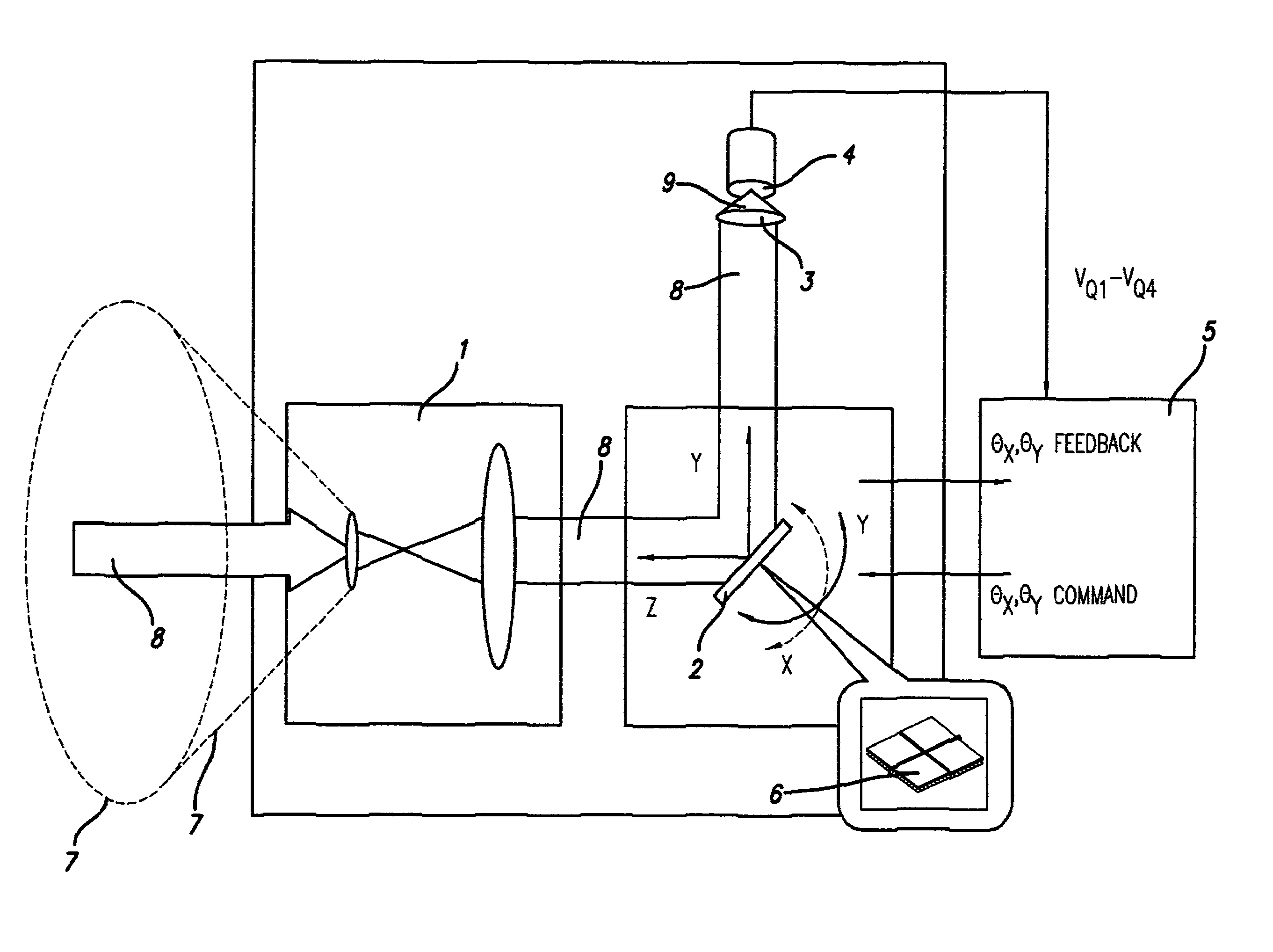
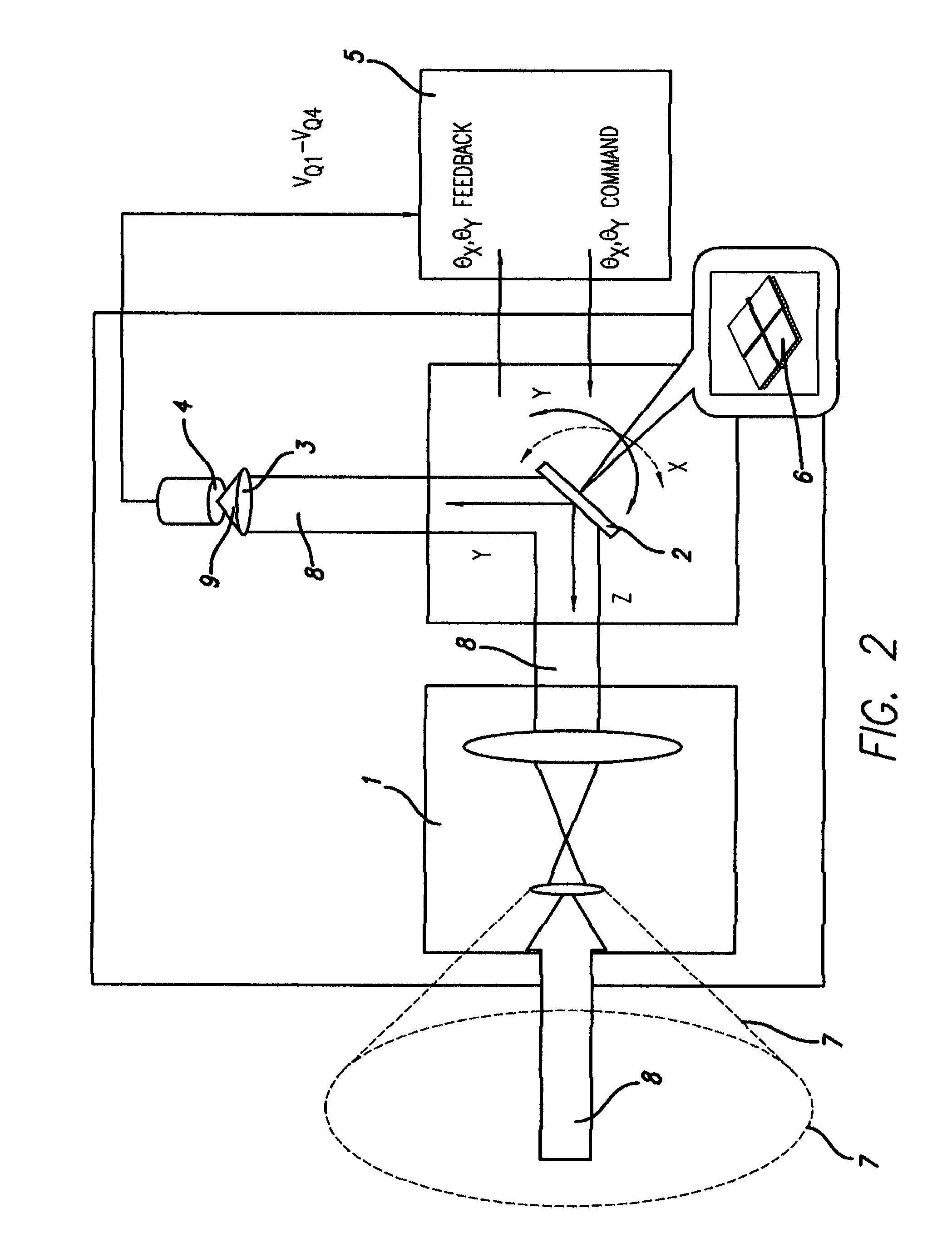
[0079]Preferred embodiments of the invention include an afocal MEMS beam-steering system with a multiple-sector sensing cell. The multisector cell may have four sectors—i.e., may be a four-sector cell or so-called “quad cell”, as described in the “BACKGROUND” section of this document—or may have a different number of sectors. A higher number, in particular, facilitates independent discrimination and analysis of two or more incident beams; however, a sensor having three sectors is also workable and within the scope of the invention.

[0080]The multisector cell (e.q. quad sensor) at least initially sees the entire field-of-view (“FOV”) and receives the incoming laser beam, preferably focused sharply. Ideally it is focused to a substantially diffraction-limited spot.

[0081]Use of a sharp focus departs very dramatically and surprisingly from the conventional practice, introduced in the “BACKGROUND” section, of defocusing the beam to facilitate operation of a quad cell. The larger spot size...


PUM


Abstract

A light beam is detected/localized by multisector detector—quad-cell, or 5+ sectors handling plural beams. Preferences: Beams focus to diffraction limit on the detector, which reveals origin direction by null-balance—shifting spots to a central sector junction, and measuring shifts to reach there. One or more MEMS reflectors, and control system with programmed processor(s), sequence the spot toward center: following a normal to an intersector boundary; then along the boundary. One afocal optic amplifies MEMS deflections; another sends beams to imaging optics. After it's known which sector received a spot, and the beam shifts, source direction is reported. The system can respond toward that (or a related) direction. It can illuminate objects, generating beams reflectively. Optics define an FOR in which to search; other optics define an FOV (narrower), for imaging spots onto the detector. The FOR:FOV angular ratio is on order of ten—roughly 180:20°, or 120:10°.

Description

RELATED DOCUMENTS[0001]This document is based in part upon, and correspondingly claims priority of, U.S. application Ser. No. 11 / 409,529 filed Apr. 21, 2006 and its precursor Provisional Patent Application 60 / 643,867 filed Jan. 13, 2005. Other related documents include, inter alia:[0002]Kane, provisional application Ser. 60 / 433,301 and corresponding PCT application PCT / US03 / 39535 “OPTICAL SYSTEM”;[0003]Kane, provisional application Ser. 60 / 381,286 “MEMS BEAM STEERING AND SHARED APERTURE OPTICAL SYSTEM”, also incorporated by reference in the provisional application and its corresponding PCT application that are mentioned immediately above;[0004]Kane et al., application serial 10 / 142,654 “HIGH-SPEED, LOW-POWER OPTICAL MODULATION APPARATUS AND METHOD”, and three provisional applications incorporated by reference therein, namely 60 / 289,883, 60 / 327,759 and 60 / 327,760.All are wholly incorporated by reference into this document.FIELD OF THE INVENTION[0005]The invention relates generally to...

Claims


Application Information

Patent Timeline
Patent Type & Authority Patents(United States)
IPC IPC(8): G01C1/00
CPCG02B26/0833G02B26/105G01C1/00
Inventor KANE, DAVID M.SELWYN, PHILIP
Owner ARETE ASSOCIATES INC
Why Eureka
Try Eureka