Diffusion barrier in a delivery apparatus for pressurized medical liquids

a technology of delivery apparatus and pressure liquid, which is applied in the direction of medical atomizers, inhalators, respirators, etc., can solve the problems of affecting the delivery volume, affecting the repeatability and accuracy of the delivery of medical liquid into the breathing gas, and more difficult problems

Inactive Publication Date: 2012-06-26
MAQUET CRITICAL CARE
View PDF17 Cites 2 Cited by
  • Summary
  • Abstract
  • Description
  • Claims
  • Application Information

AI Technical Summary

Benefits of technology

[0022]The invention is further based on the fact that time to saturation of a liquid with dissolved pressurizing gas is largely dependent on the size of the area of the liquid surface that is in direct contact with the pressurizing gas. In accordance with the invention a prolonged diffusion time is achieved by minimizing the medical liquid surface area that is in exposed to the pressurizing gas by means of a floating diffusion barrier that is configured to cover substantially the whole surface of the medical liquid in the reservoir. The barrier prevents diffusion of pressurizing gas into the medical liquid.
[0024]According to another aspect of the invention, the floating diffusion barrier is configured to freely follow the surface of the medical liquid as it sinks when doses are delivered and rises when the reservoir is refilled. For this purpose and for the purpose of minimizing the above mentioned gap between the diffusion barrier and the inner wall of the reservoir, the diffusion barrier is preferably shaped as a convex lens with a thin peripheral section in the part of the lens shaped diffusion barrier that is close to the inner wall of the reservoir. This has the effect to prevent the diffusion barrier from sticking to the inner wall of the reservoir in case that the diffusion barrier accidentally gets into an angled position with regard to the horizontal plane of the medical liquid surface.
[0025]The latter aspect may be further enhanced by configuring the floating diffusion barrier such that it has a centre of gravity located below the plane defined by the peripheral section and such that the barrier has a balanced floating characteristic.
[0027]Furthermore, the diffusion barrier enables refilling of medical liquid in a more controlled way. The barrier will prevent the medical liquid from being stirred up and also prevent bubbles from entering the medical liquid already present in the reservoir.

Problems solved by technology

In practice, however, a part of the pressurizing gas dissolves in the liquid, which in its turn affects the delivered volume due to the fact that bubbles of gas appear in the injector and in its inlet ducts as well as in or in the vicinity of possible filters.
In clinical practice, vaporizers are often used in lengthy surgical operations during which pressurizing gas thus dissolve in the medical liquid and thereby affects the repeatability and accuracy of the delivered dose of the medical liquid into the breathing gas.
However, it is always an aim for the anesthesiologist to maintain anesthesia with as low dose as possible and to have an accurate control of the process, which is more difficult if the delivered dose increases over time without changing the settings of the apparatus.
Another problem is that bubbles that are created through a pressure drop in the injector can get jammed for some types of injectors.
However, this solution is complicated and expensive due to high demands on the materials used and the limited life span of the used components.
Moreover, this prior art does not overcome the problem of diffusion of gas into the anesthetic liquid since the liquid reservoir is connected to an air tube for admitting inlet of air at atmospheric pressure in order to compensate for a negative pressure drop arising when liquid is pumped out of the reservoir.
This may for example occur if the differential pressure between the primary and the secondary reservoirs is accidentally unbalanced with a higher pressure in the primary reservoir than in the secondary reservoir.
Although the float in the secondary reservoir would prevent its liquid content from becoming saturated with pressurizing gas, there is nothing to prevent saturation in the main, primary reservoir.
This piece of prior art does not recognize the problem nor provide a solution with regard to repeatability and accuracy of the delivered dose due to diffusion of pressurizing gas in the medical liquid and there is no teaching in EP 1 300 172 that would give guidance to solve that problem.
An important issue for this prior art is that the separating device should be possible to introduce through an inspection opening, usually a manhole.
Thus, none of the prior art addresses the problem of repeatability and accuracy of delivered dose in a medical delivery apparatus with regard to diffusion of pressurizing gas into a medical liquid.

Method used


Image

  • Diffusion barrier in a delivery apparatus for pressurized medical liquids
  • Diffusion barrier in a delivery apparatus for pressurized medical liquids
  • Diffusion barrier in a delivery apparatus for pressurized medical liquids

Examples


Embodiment Construction

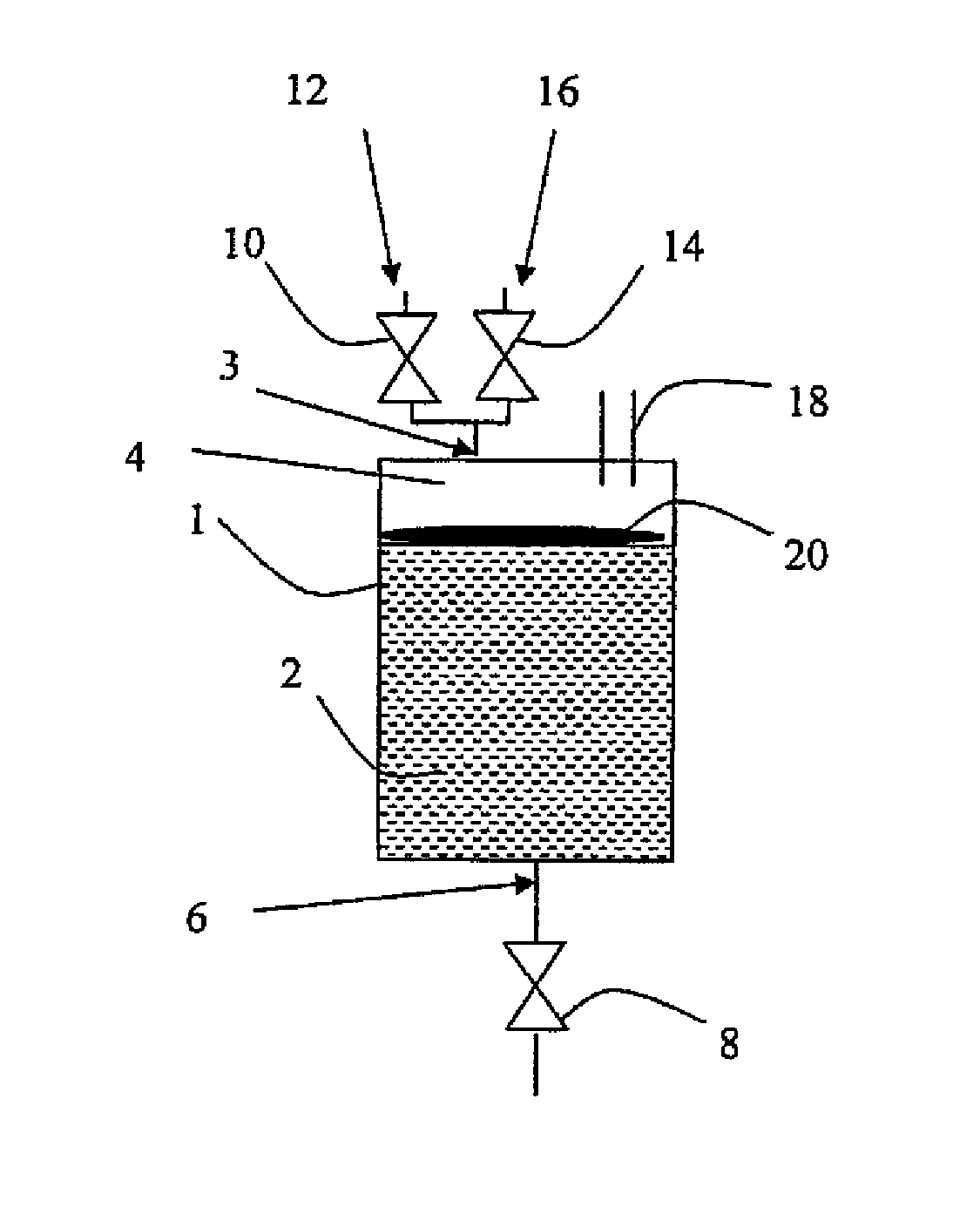
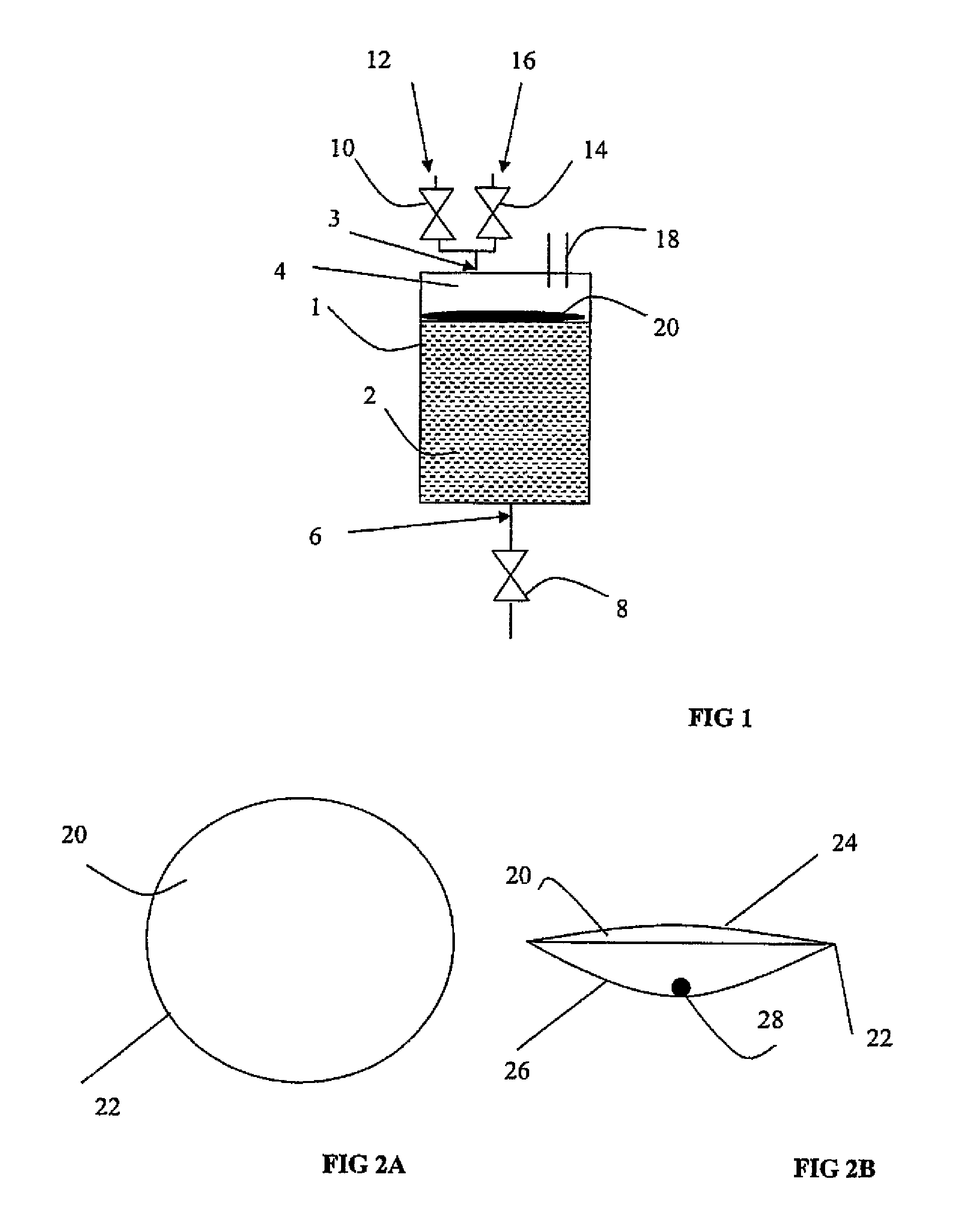
[0033]FIG. 1 shows the invention applied in an apparatus for pressurizing a medical liquid with a reservoir 1 for a medical liquid 2. The reservoir has preferably and exemplified herein the shape of a cylinder. The reservoir 1 is in its upper part provided with an inlet 3 for pressurized gas that is controllably inlet through a gas inlet valve 10 from a source 12 of pressurized gas. The inlet 3 is also used for controllable evacuation of gas from the reservoir through a gas outlet valve 14 to a gas evacuation system 16. The invention is typically applied in an anesthesia system, in which case the gas pressure provided to the reservoir 1 is preferably the driving pressure of the anesthesia system. This driving gas pressure usually has a suitable somewhat higher level than the delivery pressure chosen to fit the individual anesthesia system.

[0034]The reservoir 1 is in its lower part provided with an outlet 6 for egress of pressurized medical liquid via a controllable valve 8 that can ...


PUM


Abstract

A delivery apparatus for pressurized medical liquids has a reservoir for medical liquid and a pressurizing means configured for pressurizing medical liquid to a driving pressure; with a diffusion barrier arranged to float on medical liquid in the reservoir and disposed to cover substantially the entire surface of the medical liquid in the reservoir for the purpose of preventing diffusion of gas present in the reservoir into the medical liquid.

Description

BACKGROUND OF THE INVENTION[0001]1. Field of the Invention[0002]The present invention relates in general to delivery apparatus for pressurized medical liquids and in particular to an apparatus for pressurizing a medical liquid to a delivery pressure.[0003]2. Description of the Prior Art[0004]In delivery apparatuses for pressurized medical liquids it is known to maintain a medical liquid in a reservoir at a delivery pressure by means of pressurized gas. The gas is inlet to the reservoir from a pressurized gas source. In the reservoir the gas exerts its pressure on the surface of the medical liquid and the pressurized liquid is delivered through a controllable outlet. Such an apparatus is used for example in a vaporizer for liquid anesthetic wherein a delivery apparatus delivers the liquid via an injector coupled to the outlet and into a flow of breathing gas. In this kind of use it is important that the delivery apparatus is capable of delivering a certain volume of liquid with a hig...

Claims


Application Information

Patent Timeline
Patent Type & Authority Patents(United States)
IPC IPC(8): A61M11/00A61M15/00A61M16/00
CPCA61M11/02A61M16/18
Inventor AHLMEN, CHRISTERLARSSON, AKE
Owner MAQUET CRITICAL CARE
Why Eureka
Try Eureka