Digital time base generator and method for providing a first clock signal and a second clock signal

a digital time base and clock signal technology, applied in oscillator generators, pulse techniques, instruments, etc., can solve the problems of time delay variations over temperature, unpredictable phase difference between clock signals, measurement time is increased, etc., to achieve accurate calculation, accurate control, and minimize jitter

Active Publication Date: 2012-06-26
SIEMENS AG
View PDF14 Cites 4 Cited by
  • Summary
  • Abstract
  • Description
  • Claims
  • Application Information

AI Technical Summary

Benefits of technology

[0013]Consequently, time base generator and method in accordance with the invention provides a number of advantages. First, the start conditions can be accurately controlled. Additionally, it is possible to start at any negative delay to allow settling time and accurate measurements around zero delay.
[0014]Unlike in other conventional digital time base circuits, the detection of a zero delay in accordance with the time base generator and method of the invention is not necessary because the timing of all circuits can be accurately calculated. Here, the timing of all signals is very accurate and the jitter is minimized by utilizing crystal oscillators and (synchronous) digital circuits.

Problems solved by technology

However, as the oscillators start up, the phase difference between the clock signals is unpredictable.
Zero phase detector errors may diminish the merits of the digital solution and the measurement time is increased due to the necessity to add a waiting time for zero phase detection.
The thermal drift of the components results in time delay variations over temperature.
However, the analogue signals having slower variation will still produce a larger jitter from the voltage noise than the digital signals having fast transitions.

Method used


Image

  • Digital time base generator and method for providing a first clock signal and a second clock signal
  • Digital time base generator and method for providing a first clock signal and a second clock signal
  • Digital time base generator and method for providing a first clock signal and a second clock signal

Examples


Embodiment Construction

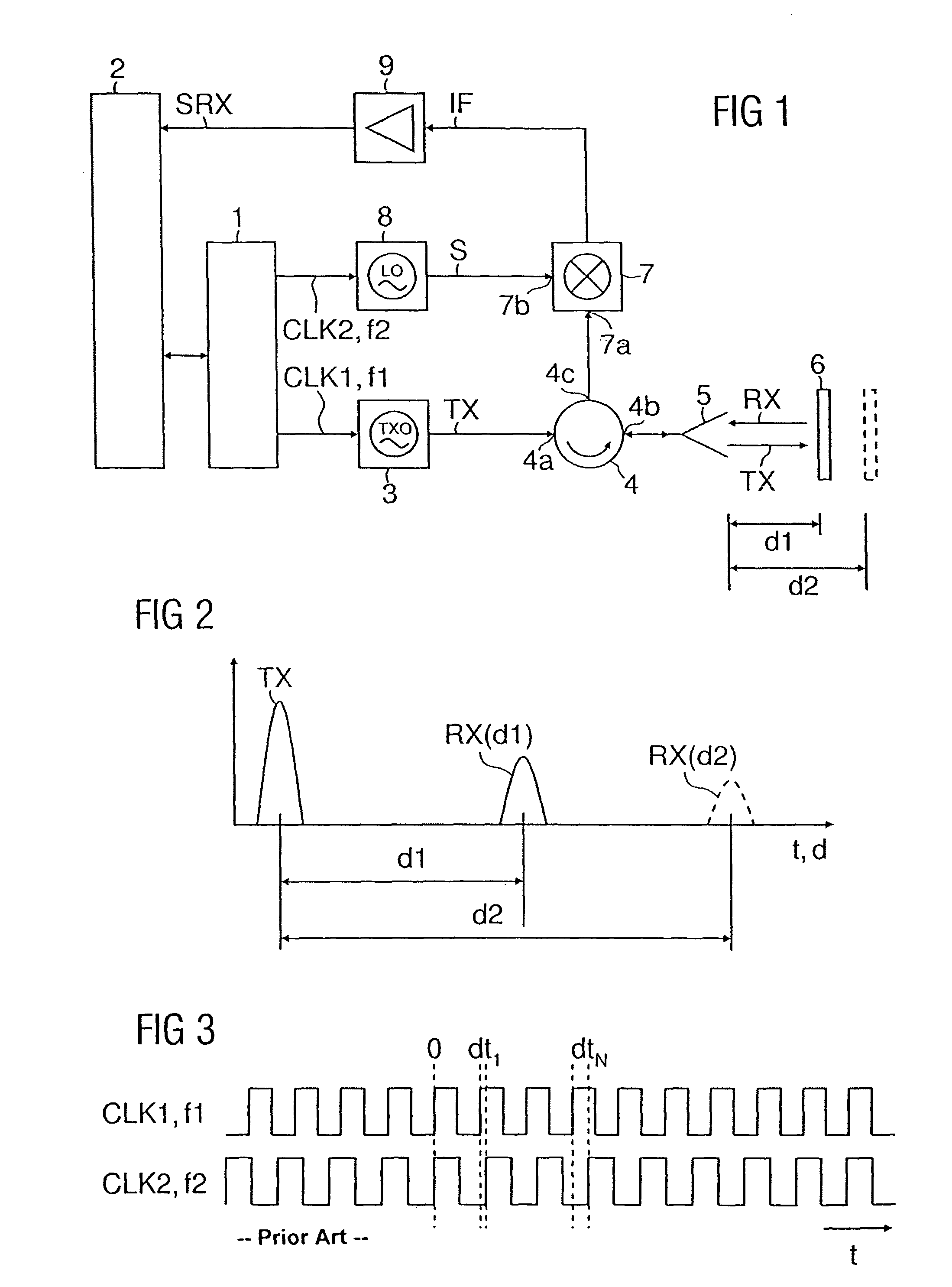
[0023]With reference to FIG. 1, which is an exemplary illustration of the basic components of a pulse radar ranging system, the system comprises a digital time base generator 1 in accordance with the invention. The time base generator 1, which is under control of a microcontroller 2, generates a first clock signal CLK1 at a first clock frequency f1 in the MHz range. The first clock signal CLK1 triggers a transmit oscillator 3 for generating microwave transmit pulses TX with a pulse repetition rate equal to the first clock frequency f1. The transmit pulses TX may have a duration of 1 ns and a frequency in the GHz range. The transmit oscillator 3 is coupled to a first port 4a of a directional coupler means comprising a four-port circulator 4, a second port 4b of which is coupled to an antenna 5. The transmit pulses TX are transmitted through the circulator 4 and the antenna 5 to a target 6, such as the surface of a fill material in a container. The target 6 reflects the transmit pulse...


PUM


Abstract

A digital time base generator and method for providing a first clock signal and a second clock signal in which a base clock signal having a base frequency is generated to provide two clock signals of slightly different frequencies with defined time or phase delay. Here, the base frequency is divided by a first integer to produce a first auxiliary signal, the frequency of the first auxiliary signal is multiplied by a factor to obtain the first clock signal, the base frequency is further divided by a second integer to produce a second auxiliary signal, and the frequency of the second auxiliary signal is multiplied by the factor to obtain the second clock signal.

Description

BACKGROUND OF THE INVENTION[0001]1. Field of the Invention[0002]The present invention relates to time base generators and, more particularly, to a digital time base generator and a method for providing a first clock signal and a second clock signal.[0003]2. Description of the Related Art[0004]U.S. Pat. No. 4,521,778 discloses pulse radar ranging systems which provide distance or level measurement based on the direct measurement of the running time of microwave pulses transmitted to and reflected from a target, e. g., the surface of a fill material in a container. The running time for distances of a few meters is in the nanosecond range. Consequently, a special time transformation procedure is required to enable these short time periods to be measured. Here, the microwave pulses are transmitted to the target at a repetition rate or transmit clock frequency which is given by a transmit clock generator. In a signal mixer, the received echo pulses reflected from the target are sampled b...

Claims


Application Information

Patent Timeline
Patent Type & Authority Patents(United States)
IPC IPC(8): H03K21/00
CPCG01S7/288H03K5/15006H03L7/06H03L7/23
Inventor BURCEA, GEORGE
Owner SIEMENS AG
Why Eureka
Try Eureka