
Laminated ceramic capacitor

a ceramic capacitor and laminated technology, applied in the direction of fixed capacitors, stacked capacitors, fixed capacitor details, etc., can solve the problems of reduced dielectric layers, low relative dielectric constant, and gradual decrease of insulation resistan

Active Publication Date: 2012-06-26
KYOCERA CORP
View PDF18 Cites 16 Cited by
  • Summary
  • Abstract
  • Description
  • Claims
  • Application Information

AI Technical Summary

Benefits of technology

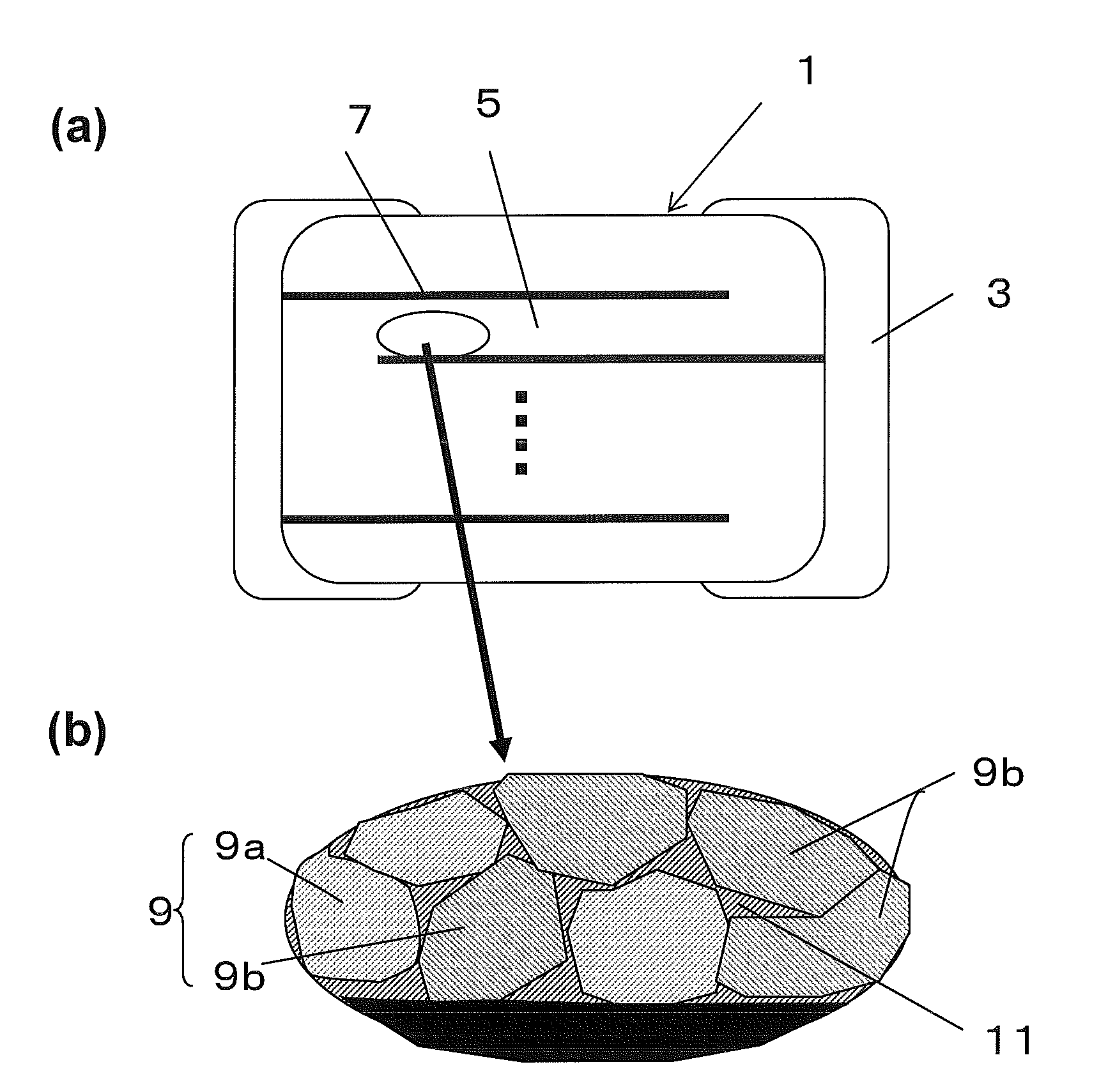
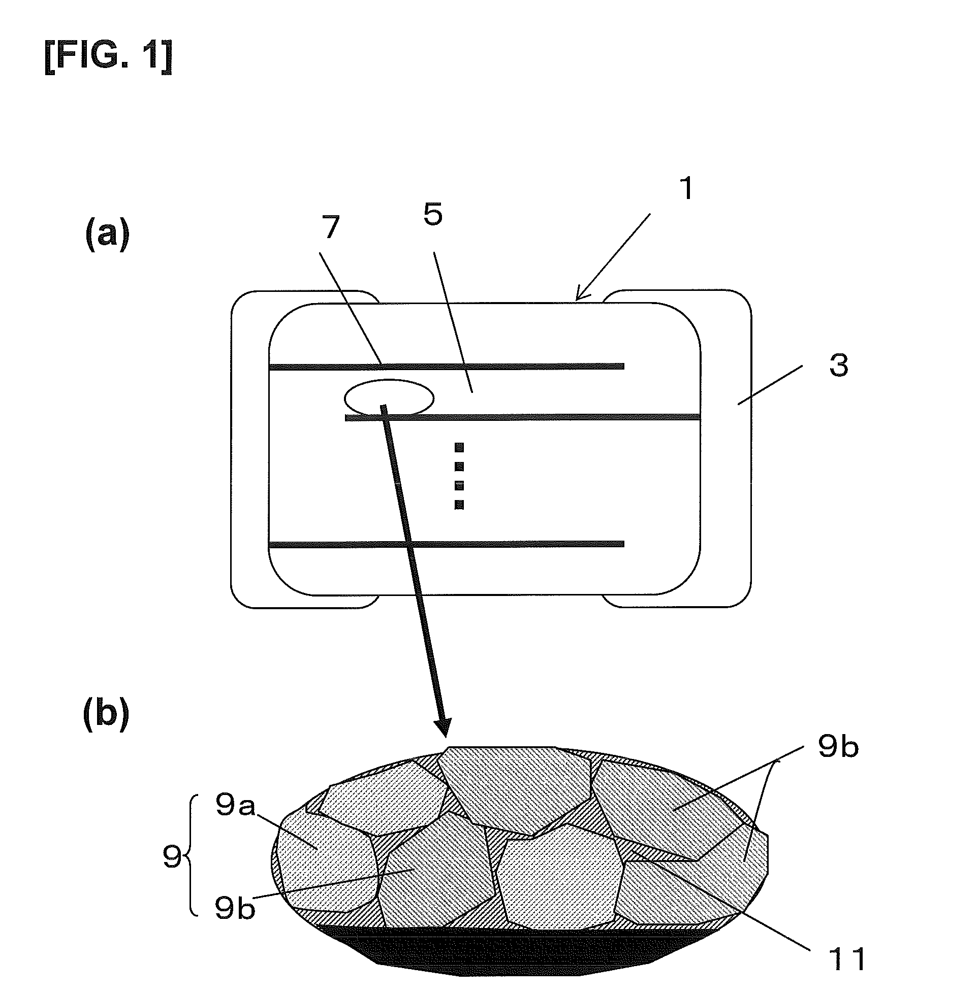
The present invention relates to a multilayer ceramic capacitor with small size and high capacitance. The invention provides a solution to the problem of reducing insulation resistance with time during a high-temperature load test and maintaining high insulation resistance after firing. The invention achieves this by using a dielectric ceramic containing barium titanate as a main component and containing calcium in a controlled manner. The dielectric layers of the capacitor have crystal grains with different calcium concentrations, resulting in a high insulation resistance and a low relative dielectric constant. The invention also includes a method for producing the multilayer ceramic capacitor with high efficiency.

Problems solved by technology

However, the multilayer ceramic capacitor disclosed in Patent Document 1 above and having dielectric layers constituted by the composite grains has a problem in that the insulation resistance gradually decreases while the capacitor is left in a high temperature environment for evaluation of the high temperature loading life.
Additionally, when the multilayer ceramic capacitor is produced, a capacitor body immediately after firing at a temperature of about 1200° C. in a reducing atmosphere and before formation of external electrodes has dielectric layers that are reduced and do not have practical insulation resistance and have a low relative dielectric constant.

Method used


Image

  • Laminated ceramic capacitor
  • Laminated ceramic capacitor
  • Laminated ceramic capacitor

Examples


examples

[0078]The following material powders were prepared and mixed in accordance with the proportions shown in Table 1: a BT powder, a BCT powder (Ba0.95Ca0.05TiO3), MgO, Y2O3, Dy2O3, Ho2O3, Tb2O3, MnCO3 and V2O5. These material powders had a purity of 99.9%. The BT powder and the BCT powder had a mean particle diameter of 100 nm in Sample Nos. 1 to 28 and 30 to 40. In Sample No. 29, the BCT powder had a mean particle diameter of 0.24 μm and the BT powder had a mean particle diameter of 0.2 μm. The amounts of MgO, Y2O3, Dy2O3, Ho2O3, Er2O3, MnCO3, and V2O5 added shown in Table 1 are values with respect to 100 mol of the total amount of the BT powder and the BCT powder. The Ba / Ti ratio of the BT powder was 1.001 and the Ba / Ti ratio of the BCT powder was 1.003.

[0079]Particles of the BT powder and the BCT powder were coated with the rare-earth element by mixing the powders with an aqueous solution containing the first rare-earth element by a liquid-phase method and then heating the resulting...


PUM

PropertyMeasurementUnit
thicknessaaaaaaaaaa
temperatureaaaaaaaaaa
thicknessaaaaaaaaaa

Abstract

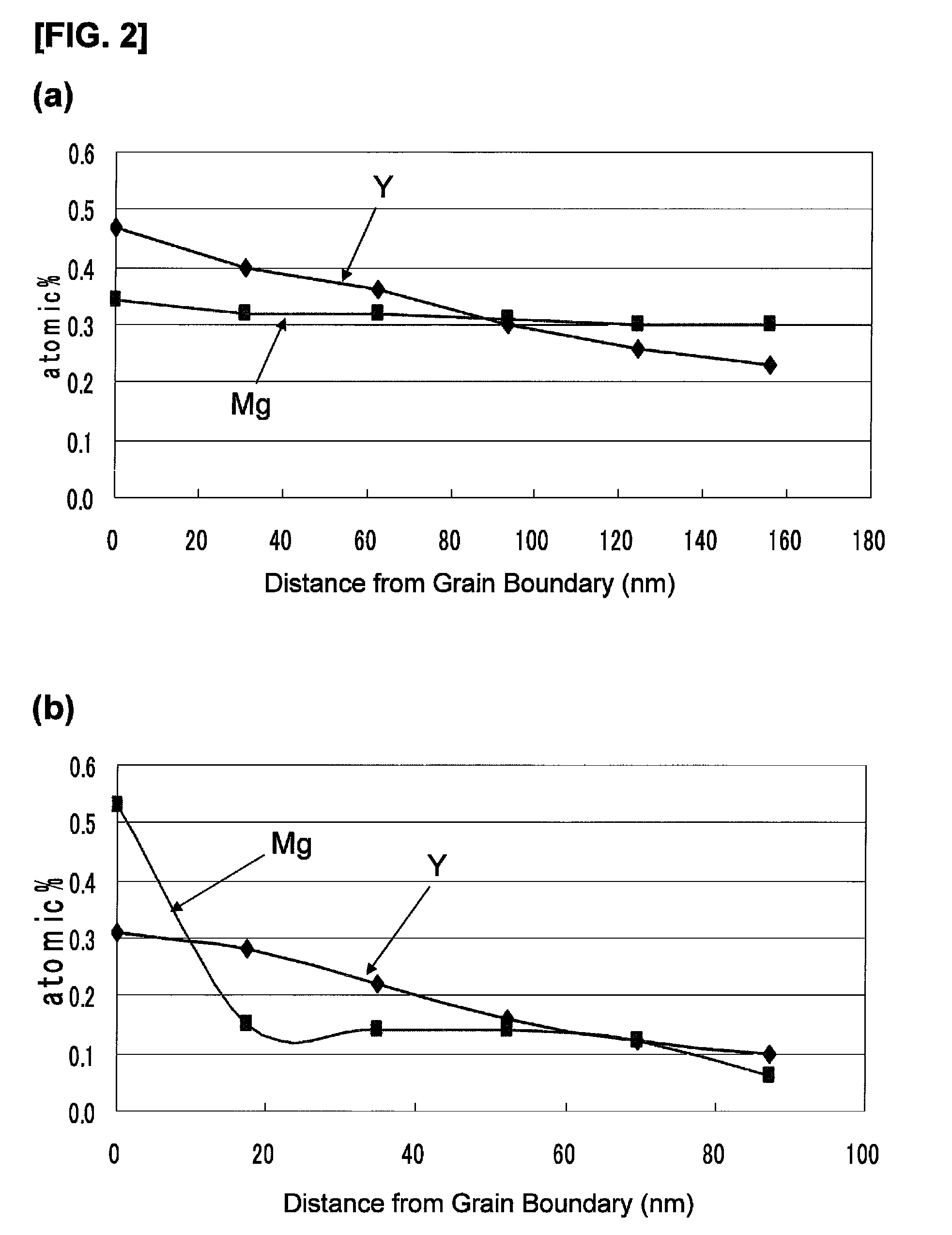
A crystal constituting a dielectric porcelain, comprised of a first crystal group composed of crystal grains of 0.2 atomic % or less calcium concentration and a second crystal group composed of crystal grains of 0.4 atomic % or more calcium concentration, wherein the ratio of concentration of each of magnesium and a first rare earth element contained in a center portion to that contained in a surface layer portion of crystal grains constituting the first crystal group is greater than the corresponding concentration ratio of crystal grains constituting the second crystal group, and wherein on a polished surface resulting from polishing of the surface of the dielectric porcelain, when the area of crystal grains of the first crystal group is referred to as a and the area of crystal grains of the second crystal group referred to as b, the ratio of b / (a+b) is in the range of 0.5 to 0.8.

Description

TECHNICAL FIELD[0001]The present invention relates to a multilayer ceramic capacitor, and, in particular, to a multilayer ceramic capacitor that has a small size and a high capacitance and includes dielectric layers constituted by barium titanate crystal grains having different Ca concentrations.BACKGROUND ART[0002]With the recent trend toward widespread use of mobile devices such as cellular phones and achievement of higher speed and higher frequency in semiconductor devices serving as main components for personal computers, there is an ever increasing demand for a multilayer ceramic capacitor having a smaller size and a higher capacitance, the multilayer ceramic capacitor being implemented in such electronic devices. To provide such a multilayer ceramic capacitor, attempts have been made to reduce the thickness of dielectric layers constituting a multilayer ceramic capacitor and to increase the number of dielectric layers stacked.[0003]For example, Patent Document 1 describes use ...

Claims


Application Information

Patent Timeline
Patent Type & Authority Patents(United States)
IPC IPC(8): H01G4/12C04B35/468
CPCH01G4/1227H01G4/30
Inventor YAMAZAKI, YOUICHIOSUZU, HIDEYUKIFUJIOKA, YOSHIHIROFUKUDA, DAISUKE
Owner KYOCERA CORP
Learn More