

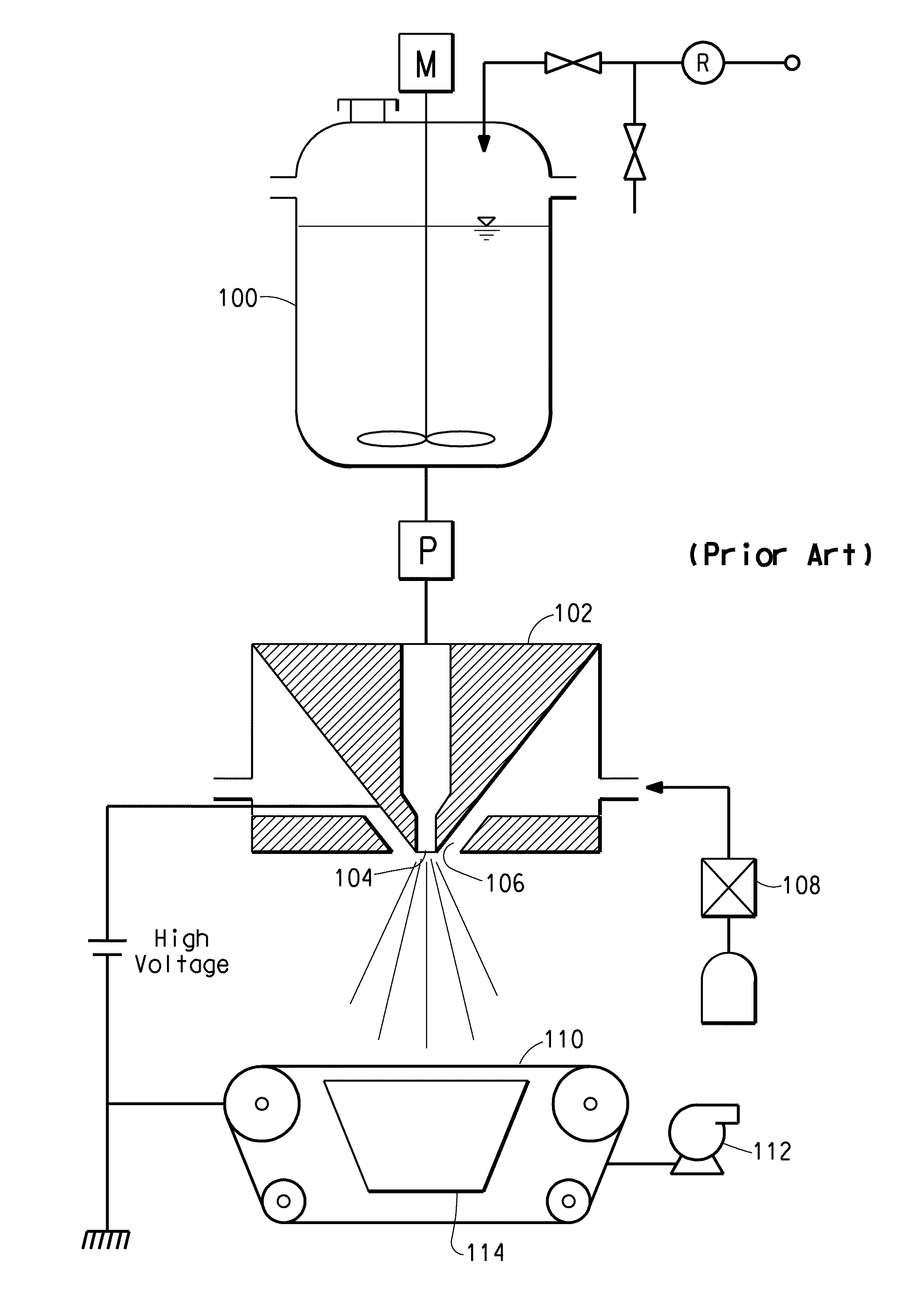
Fiber spinning process using a weakly interacting polymer
a fiber and polymer technology, applied in the field of fiber spinning process, can solve the problems of low electrical conductivity and unsuitability for electrospinning
- Summary
- Abstract
- Description
- Claims
- Application Information
AI Technical Summary
Benefits of technology
Problems solved by technology
Method used
Image

Examples
example 1
[0029]An 8 wt % solution of a poly(4-methyl-1-pentene) (DX820) having a dielectric constant of 2.1, available form Mitsui Chemical, was dissolved in methylcyclohexane using a reflux condenser. A magnetic stirrer was used to agitate the hot solution. The homogeneous solution was transferred to a sealed glass container and transported to the spin chamber. The solution was transferred into the reservoir of the spin chamber and sealed. A spinneret with a 0.4064 mm inside diameter single spinning nozzle was used. A drum collector was used to collect the sample. The spinneret was placed at a negative potential of 100 kV. The collector was grounded. The distance from the spinning nozzle exit to the collector surface was 35 cm. Air was used for the blowing gas. Nitrogen was used for the secondary gas to control the relative humidity (RH) and the temperature in the spin chamber. The flow of nitrogen was sufficient to prevent the concentration of the solvent vapor in the spin chamber from exc...
example 2
[0030]A 9 wt % solution of a polystyrene (DOW 685D) having a dielectric constant of 2.5, available form DOW, was dissolved in toluene using a reflux condenser. A magnetic stirrer was used to agitate the hot solution. The homogeneous solution was transferred to a sealed glass container and transported to the spin chamber. The solution was transferred into the reservoir of the spin chamber and sealed. A spinneret with a 0.4064 mm inside diameter single spinning nozzle was used. A drum collector was used to collect the sample. The spinneret was placed at a negative electrical potential of 100 kV. The drum collector was grounded. The distance from the spinning nozzle exit to the collector surface was 51 cm. Air was used for the blowing gas and for the secondary gas to control the RH and the temperature in the spin chamber. The RH was controlled to be less than 20%. The spin chamber temperature was close to 26° C. for the duration of the experiment. A nitrogen pressure of 0.135 MPa was u...
example 3
[0031]An 11 wt % solution of Engage 8400 (an ethylene octene copolymer) having a dielectric constant of 2.2, available from DuPont, was dissolved in methylcyclohexane using a reflux condenser. A magnetic stirrer was used to agitate the hot solution. The homogeneous solution was transferred to a sealed glass container and transported to the spin chamber. The solution was transferred into the reservoir of the spin chamber and sealed. A spinneret with a 0.4064 mm inside diameter single spinning nozzle was used. A drum collector was used to collect the sample. The spinneret was placed at a negative potential of 100 kV. The collector was grounded. The distance from the spinning nozzle exit to the collector surface was 30 cm. Air was used for the blowing gas. Nitrogen was used for the secondary gas to control the RH and the temperature in the spin chamber. The flow of nitrogen was sufficient to avoid the concentration of the solvent vapor in the spin chamber exceeding the lower explosion ...
PUM
| Property | Measurement | Unit |
|---|---|---|
| dielectric constant | aaaaa | aaaaa |
| conductivity | aaaaa | aaaaa |
| temperature | aaaaa | aaaaa |
Abstract
Description
Claims
Application Information