Control of power generation system having thermal energy and thermodynamic engine components

a technology of power generation system and control system, which is applied in the direction of mechanical power/torque control, ratio control, heat storage plant, etc., can solve the problems of inability to reconcile the disparity, ineffective photovoltaic solutions, and inability to meet the electrical and thermal energy needs of residential or commercial buildings. to achieve the effect of maximizing electric energy production or the rate of return on investment, minimizing the cost or amount of purchased electric, and maximizing the cost or efficiency of electric energy

Active Publication Date: 2012-07-17
COOL ENERGY
View PDF13 Cites 16 Cited by
  • Summary
  • Abstract
  • Description
  • Claims
  • Application Information

AI Technical Summary

Benefits of technology

[0015]In another aspect, a Stirling engine that also has the capability to operate as a heat pump could enhance the functionality of some thermal energy power systems, particularly those installed in buildings having only electric service. An electric-powered heat pump drawing heat from solar heated heat transfer fluid that is warm, but not hot enough to heat the building, will operate at a much higher theoretical coefficient of performance than if drawing heat from the cold outside air or even the ground. Using the Stirling engine for this additional function thereby increases the utilization of the engine asset.
[0017]As discussed above, the temperature difference across the Stirling engine causes the Stirling engine to operate and thereby drive an electric generator. Electricity from the generator, in turn, provides electricity for the building electric needs. The generator may directly produce the proper voltage and frequency used by the grid, which in the United States is 120 volts at 60 hertz, or may produce electricity in some other form which is then converted to the form used by the grid. The generator may thus be coupled to a building electric system (grid-tied or distributed), such as through a dedicated breaker on a conventional junction box.
[0019]The system further includes the control of the system when integrated with external energy sources and information about them, including when such an energy source, such as the electric utility grid, may act as a sink and thereby receive energy produced by the system. The system controller, for example, may thus accept and act on information regarding the price of electric power sold to as well as purchased from an electric utility. Such system inputs may be used by the controller to optimize operation of the system to maximize electric energy production or the rate of return on investment, or to minimize the cost or amount of purchased electric or thermal energy, or the amount of greenhouse gas emissions, or in respect of some metric based on combinations thereof.

Problems solved by technology

Although viable in some applications, existing photovoltaic solutions are too inefficient and cost prohibitive to be broadly adopted as an electric energy source or thermal energy source.
Similarly scaled solar thermal systems are used for space and domestic hot water heating, but have no provision for electric power generation, and cannot reconcile the disparity between the high demands for thermal energy in cold months with the high availability of thermal energy in warm months.
Because they are limited to producing only one form of energy, either electricity or heat but not both, neither solar energy platform can by itself practically address both electrical and thermal energy needs of residential or commercial buildings.
However, as the electrical demand in the building will fluctuate over time, including during a day, during a week and over a yearly seasonal cycle, the heat engine may be unable to provide the entire electrical load at some times, or may be able to supply excess electricity at other times. For example, during cloudy conditions and storms, the solar irradiation on the collector is disrupted, requiring the use of a non-solar energy source, which may include grid-supplied electricity, to meet the electric power requirements of the building.
Furthermore, it may also be desirable to use the solar thermal energy provided from a solar collector for space and water heating applications, thus creating a conflict between the need for electricity and the need for space and domestic hot water heating.

Method used


Image

  • Control of power generation system having thermal energy and thermodynamic engine components
  • Control of power generation system having thermal energy and thermodynamic engine components
  • Control of power generation system having thermal energy and thermodynamic engine components

Examples


Embodiment Construction

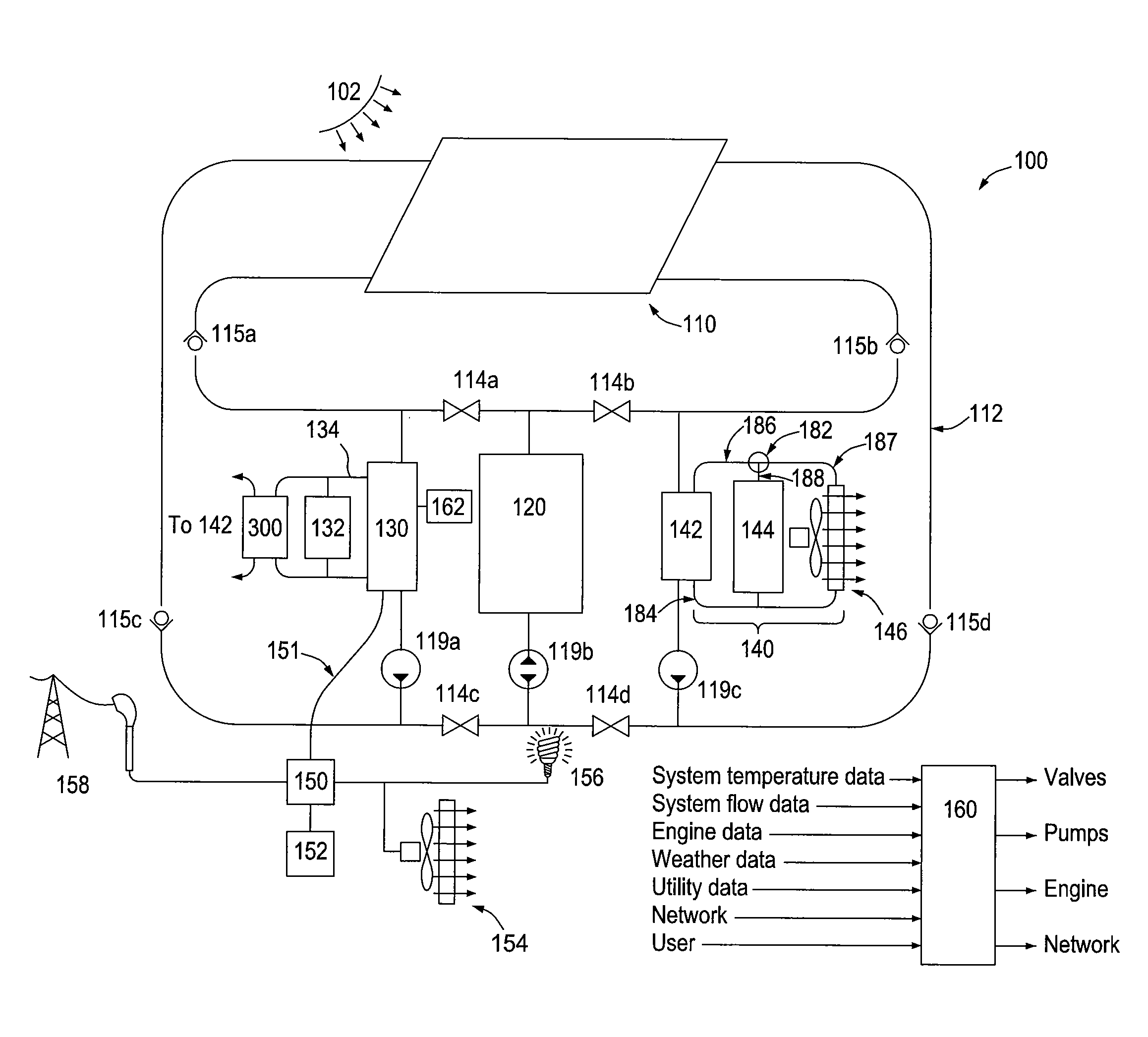
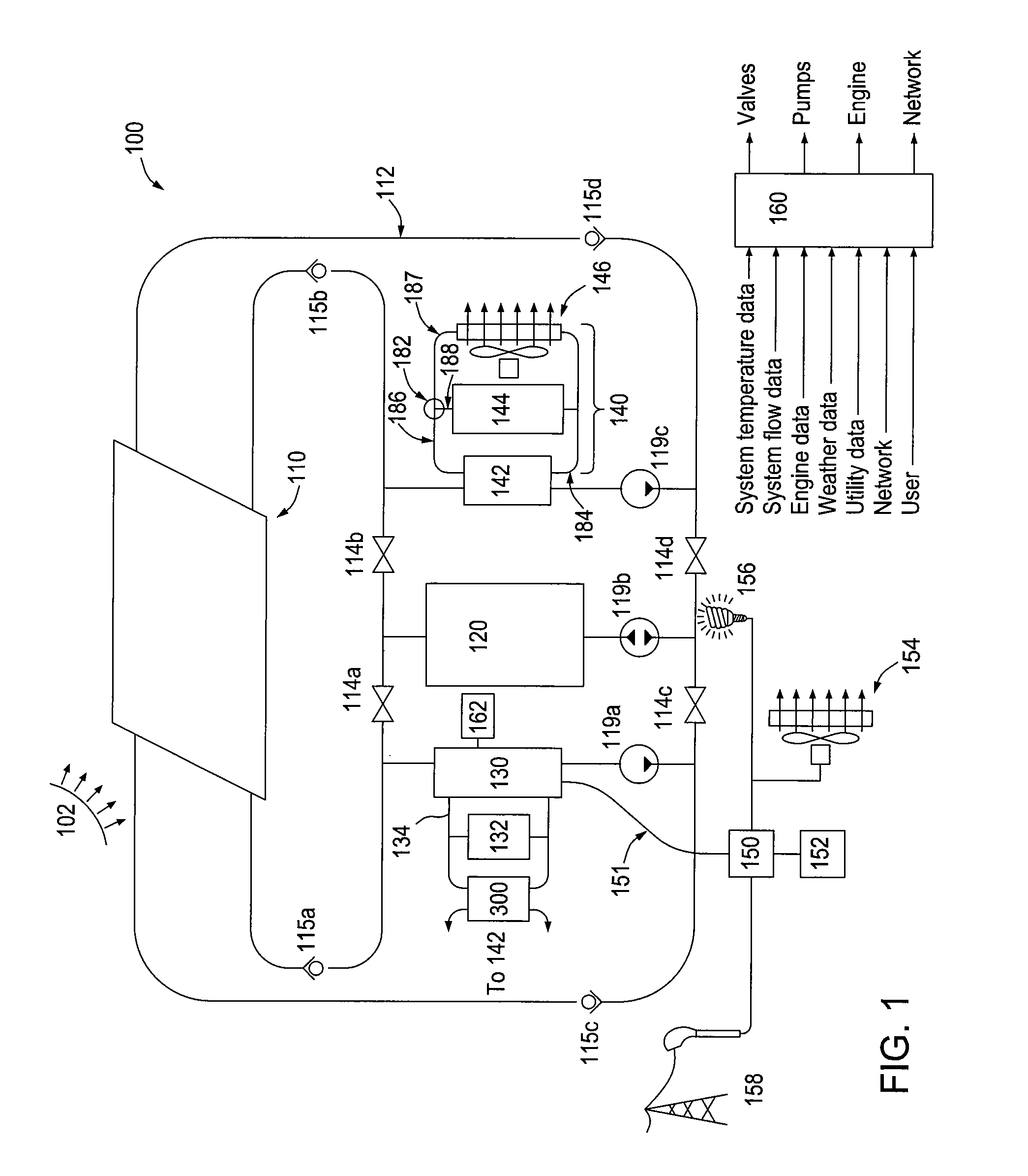
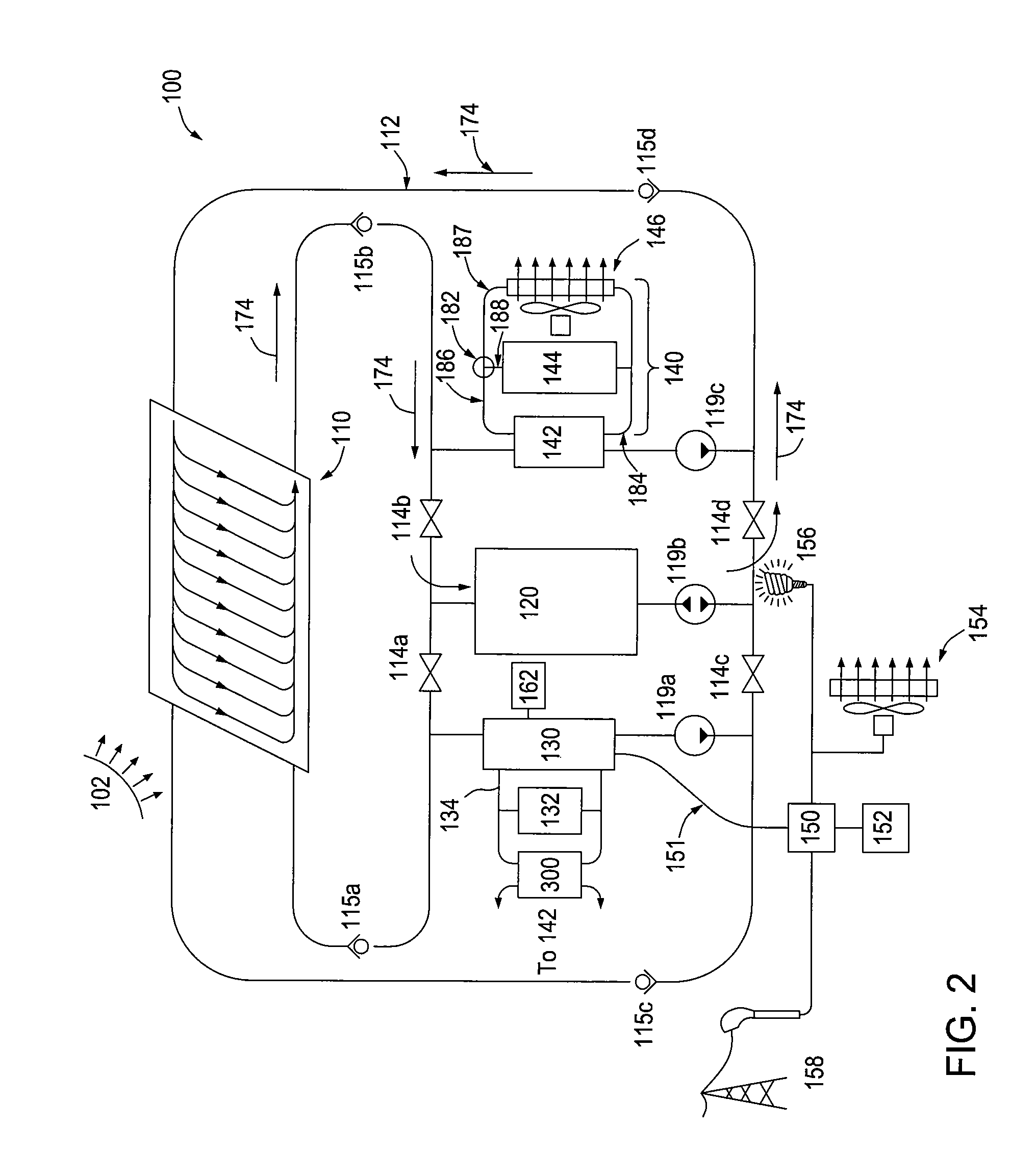
[0036]Aspects of the present invention involve a power generation system that integrates forms of alternative energy such as solar energy, geothermal energy, industrial or commercial waste heat; traditional or uninterruptible energy sources such as propane or fuel oil stored on site or as provided by connection to an electric power grid or a natural gas service; on-site energy stores; space heating and cooling demands; domestic hot water heating demands; thermodynamic engines that may generate electricity; and heat pumps. The integration involves the control of the system to account for factors external to the system, which may include past, historical, present, or forecast conditions of time of day, day of week, calendar day, weather, solar irradiance, and availability and price of energy for both sale to as well as purchase from a utility or other energy supplier, as well as factors internal to the system, which may include past, historical, present, or forecast conditions of temp...


PUM


Abstract

A thermal source provides heat to a heat engine and or one or more thermal demands, including space and water heating and heat storage. Additionally the output of the heat engine may be used for local in situ electricity needs, or directed out over the grid. A system controller monitors conditions of the components of the system, and operates that system in modes that maximize a particular benefit, such as a total accrued desired benefit obtained such as reduced electricity cost, reduced fossil fuel use, maximized return on investment and other factors. The controller may use past history of use of the system to optimize the next mode of operation, or both past and future events such as predicted solar insolation.

Description

BACKGROUND OF THE INVENTION[0001]1. Field of the Invention[0002]Aspects of the present invention generally relate to control systems for a power generation system having thermal energy and thermodynamic engine components.[0003]2. Background of the Art[0004]Environmental concerns and political and economic forces have renewed the interest in all facets of alternative energy. Many sources of alternative energy, particularly solar energy, still have tremendous potential for greater adoption. Despite the distinct advantages of emitting little or no pollution or greenhouse gasses, having an unlimited free energy supply, and being harnessed with many already proven technologies, solar energy requires further development of its technologies to make it a cost competitive energy source for heat and electricity for residences and commercial buildings compared with heat and electricity now produced by burning coal, natural gas, and oil.[0005]Solar electric generating systems suitable for distr...

Claims


Application Information

Patent Timeline
Patent Type & Authority Patents(United States)
IPC IPC(8): G05B21/00B60H1/00F28D15/00F16D31/02F01K1/00F03G6/00F03G7/00F01K27/00G05D3/12F24H9/20F24D5/00B64D11/00F24D18/00
CPCF01K3/16F24D11/001F24D19/1006F24D2200/14F24H2240/00Y02B10/20Y02E10/46Y02B30/17Y10T137/2196F24D18/00F24D2103/17F24D2101/80F24D2101/40F24D2103/13
Inventor WEAVER, SAMUEL P.SMITH, LEE S.
Owner COOL ENERGY
Why Eureka
Try Eureka