Unlock instant, AI-driven research and patent intelligence for your innovation.

Fuel cell system

a fuel cell and system technology, applied in the direction of fuel cells, electrolyte stream management, electrical equipment, etc., can solve the problems of easy corrosion of separation devices, achieve the effect of reducing the length of pipes, simple and compact structure, and efficient utilization of combustion gas hea

Active Publication Date: 2012-07-24
HONDA MOTOR CO LTD
View PDF12 Cites 0 Cited by
  • Summary
  • Abstract
  • Description
  • Claims
  • Application Information

AI Technical Summary

Benefits of technology

The present invention provides a fuel cell system with a simple and compact structure that improves heat efficiency. The system includes a fuel cell stack, heat exchanger, reformer, combustor, and casing. The fuel cell stack is heated by the heat exchanger using a heat medium, and the raw fuel is reformed to produce a fuel gas using the reformer. The combustor burns the raw fuel and exhaust gas from the fuel cell stack to produce a combustion gas as the heat medium. The casing contains the fuel cell stack, heat exchanger, reformer, and combustor. The system has a simple structure with reduced lengths of pipes, making it compact. The combustion gas is directly supplied to the fluid unit, allowing for efficient use of heat. Overall, the invention improves heat efficiency in the fuel cell system.

Problems solved by technology

Therefore, the separators tend to be corroded easily by the hot combustion gas, and carbon in the combustion gas adheres to the separators.

Method used


Image

  • Fuel cell system
  • Fuel cell system
  • Fuel cell system

Examples


first embodiment

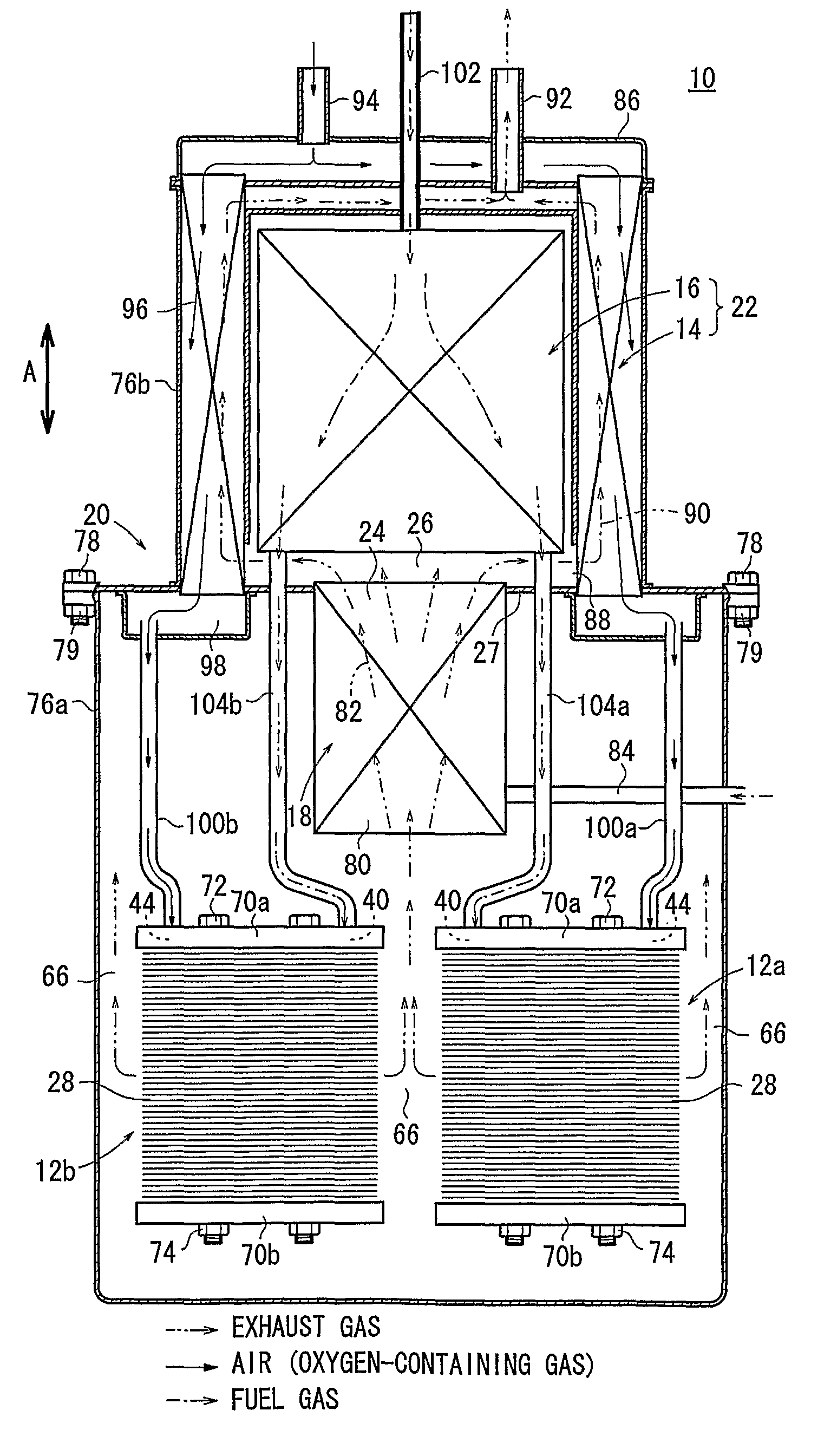
[0020]FIG. 1 is a partial cross sectional view showing a fuel cell system 10 according to the present invention.

[0021]The fuel cell system 10 is used in various applications, including stationary and mobile applications. For example, the fuel cell system 10 is mounted on a vehicle. The fuel cell system 10 includes a pair of fuel cell stacks 12a, 12b, a heat exchanger 14, a reformer 16, a combustor 18, and a casing 20. The heat exchanger 14 heats an oxygen-containing gas before it is supplied to the fuel cell stacks 12a, 12b. The reformer 16 reforms a raw fuel chiefly containing hydrocarbon to produce a fuel gas. The combustor 18 burns the raw fuel and an exhaust gas to produce a combustion gas. The exhaust gas is discharged from the fuel cell stacks 12a, 12b after consumption in the power generation. The fuel cell stacks 12a, 12b, the heat exchanger 14, the reformer 16, and the combustor 18 are disposed in the casing 20.

[0022]In the casing 20, a fluid unit 22 including at least the ...

second embodiment

[0052]In the second embodiment, the fuel cell stacks 12a, 12b, and the fluid unit 22 can be positioned adjacent to one another. The overall dimension of the fuel cell system 120 in the direction indicated by the arrow A is reduced significantly.

[0053]The combustor 126 is positioned between the fuel cell stacks 12a, 12b, and extends in the direction indicated by the arrow A. Thus, by radiation heat from the combustor 126, the fuel cell stacks 12a, 12b are heated suitably, and improvement in heat efficiency is achieved advantageously.

[0054]Further, also in the second embodiment, all of the exhaust gas discharged from the fuel cell stacks 12a, 12b necessarily flows through the combustor 126. In the same manner as in the case of the first embodiment, the combustion gas discharged from the combustor 126 is purified, and the heat generated in combustion of the unburned fuel gas can be utilized for heating the fuel cell stacks 12a, 12b, and the fluid unit 22.

third embodiment

[0055]FIG. 4 is a partial cross sectional view showing a fuel cell system 140 according to the present invention.

[0056]The fuel cell system 140 has a casing 142. The casing 142 includes a first case unit 144a containing the fuel cell stacks 12a, 12b and a second case unit 144b containing the fluid unit 22. A combustor 148 is provided between the first case unit 144a and the second case unit 144b through connection casing units 146a, 146b.

[0057]An evaporator 150 for evaporating water and a reformer (preliminary reformer) 152 using the water vapor (steam) and a raw fuel (e.g., city gas) for steam reforming of the raw fuel are provided adjacent to each other at the center of the second case unit 144b.

[0058]In the third embodiment, the fuel cell stacks 12a, 12b are connected to the fluid unit 22 through the combustor 148 provided between the fuel cell stacks 12a, 12b and the fluid unit 22. In the structure, the same advantages as in the case of the first and second embodiments can be ...


PUM

PropertyMeasurementUnit
operating temperatureaaaaaaaaaa
ion-conductiveaaaaaaaaaa
temperatureaaaaaaaaaa

Abstract

A fuel cell system includes a fuel cell stack, a heat exchanger for heating an oxygen-containing gas using a heat medium before the oxygen-containing gas is supplied to the fuel cell stack, a reformer for reforming a raw fuel chiefly containing hydrocarbon to produce a fuel gas to be supplied to the fuel cell stack, a combustor for burning a raw fuel and an exhaust gas discharged from the fuel cell stack after consumption in power generation reaction to produce a combustion gas as the heat medium, a casing containing the fuel cell stack, the heat exchanger, the reformer, and the combustor. A combustion gas outlet of the combustor is directly opened to a combustion gas inlet of the fluid unit.

Description

RELATED APPLICATIONS[0001]This application is a 35 U.S.C. 371 national stage filing of International Application No. PCT / JP2007 / 058390, filed 11 Apr. 2007, which claims priority to Japanese Patent Application No. 2006-112039 filed on 14 Apr. 2006 in Japan. The contents of the aforementioned applications are hereby incorporated by reference.TECHNICAL FIELD[0002]The present invention relates to a fuel cell system including a fuel cell stack formed by stacking a plurality of fuel cells. Each of the fuel cells is formed by stacking an electrolyte electrode assembly and a separator. The electrolyte electrode assembly includes an anode, a cathode, and an electrolyte interposed between the anode and the cathode.BACKGROUND ART[0003]Typically, a solid oxide fuel cell (SOFC) employs an electrolyte of ion-conductive solid oxide such as stabilized zirconia. The electrolyte is interposed between an anode and a cathode to form an electrolyte electrode assembly. The electrolyte electrode assembly ...

Claims


Application Information

Patent Timeline
Patent Type & Authority Patents(United States)
IPC IPC(8): H01M8/04
CPCH01M8/04276H01M8/0618H01M8/0625H01M8/2475H01M2008/1293Y02E60/50Y02E60/525
Inventor TSUNODA, TADASHI
Owner HONDA MOTOR CO LTD