
Wireless passive temperature sensor

a passive temperature sensor and wireless technology, applied in the field of thermodynamic measurement, can solve the problems of increasing the fabrication cost during dicing and packaging, affecting the accuracy of sensing measurements, so as to eliminate licensing problems

Active Publication Date: 2012-08-14
NAT TECH & ENG SOLUTIONS OF SANDIA LLC
View PDF18 Cites 25 Cited by
  • Summary
  • Abstract
  • Description
  • Claims
  • Application Information

AI Technical Summary

Benefits of technology

[0008]The wireless, SAW-based temperature sensor employs a relatively inexpensive, pulsed radar-type measurement, but still allows monitoring of wide temperature ranges (e.g., less that −60° C. to greater than 190° C.) with uncertainties on the order of 0.9° C. In addition, the sensor provides a primary measurement of the thermal coefficient of frequency of a substrate, allowing the measurement to be made independently of the physical distance from the powered reader to the measurement tag, within the limits of the signal-to-noise ratio. Sensors can be fabricated with different center frequency bands and transit delays allowing arrays of independent sensors to be deployed and measured. These SAW-based sensors can be designed to operate in the 915 MHz industrial, scientific, and medical (ISM) band, eliminating licensing issues for the readout hardware.

Problems solved by technology

Not only do the wires provide a thermal conduction path that disturbs the measurement, but the wires also change the dynamics of the body during acceleration and shock testing due to their added mass.
This bit sequence requires each part on the wafer to have a unique photo-mask and thus increases fabrication cost during dicing and packaging due to tracking requirements on that unique part.
In addition, some of the energy received by the SAW device via the antenna is used for the identification and thus reduces the energy available for the sensing measurement.
This type of sensor response is good for monitoring pressure, strain, and torque but is limited by the expense and portability of the readout hardware.
Further, SAW devices typically operate at frequencies in the range of 100 MHz to several GHz, making the monitoring of the phase and individual waves impractical for portable, inexpensive systems.

Method used


Image

  • Wireless passive temperature sensor
  • Wireless passive temperature sensor
  • Wireless passive temperature sensor

Examples


Embodiment Construction

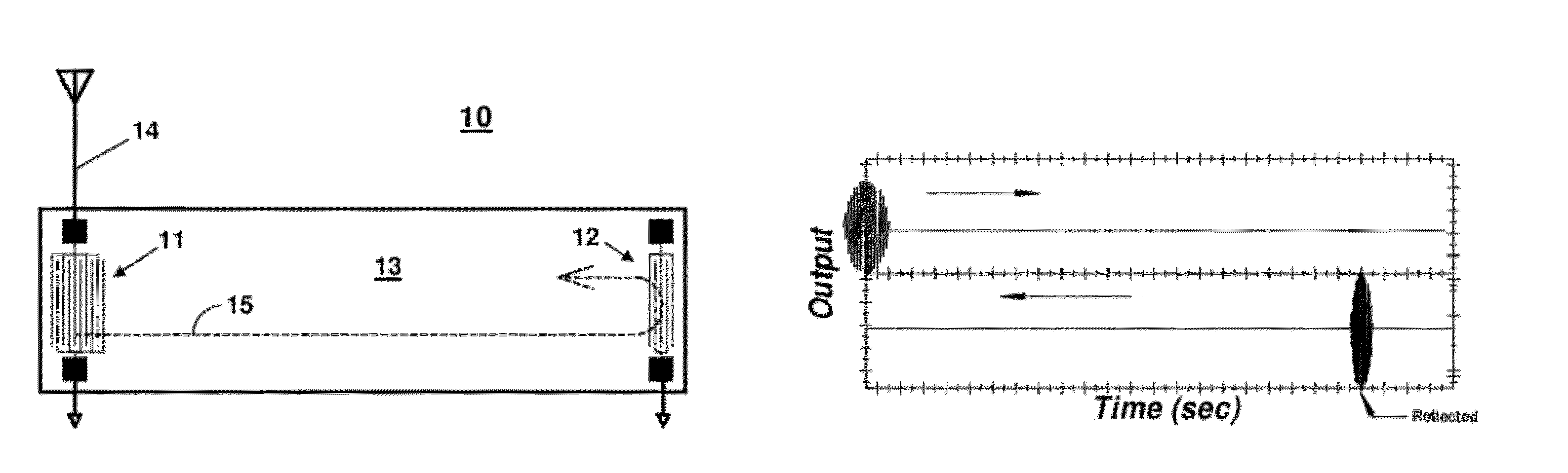
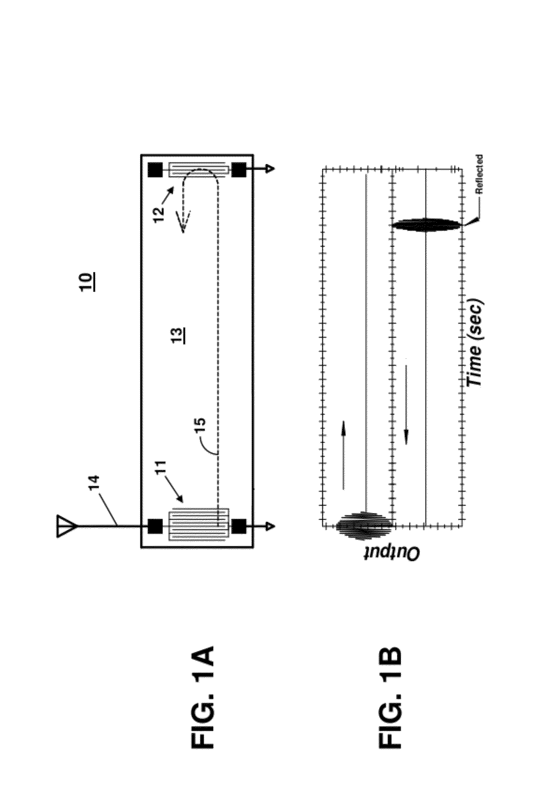
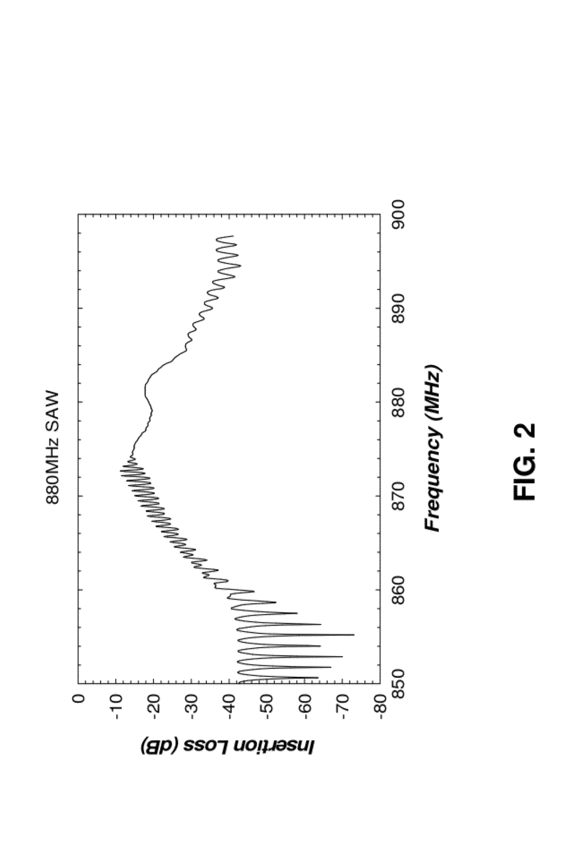
[0023]The wireless passive temperature sensor of the present invention is based on the change in minimum insertion loss of a SAW delay line that allows for large arrays of self-identifying sensors to be pre-positioned for thermal measurement of a structure. The sensors do not require batteries that add unacceptable mass to the structure or wires to retrieve the data, enabling remote sensing. These sensors have a very linear response over a range of less than −60° C. to greater than 190° C. and allow wireless measurements that eliminate the mechanical and thermal disturbance that occur for hard-wired systems. Variation of the SAW characteristic delay and center frequency allow the manufacture of inexpensive, robust, self-identifying sensor element arrays that can be read using a single antenna and data acquisition system. Therefore, a measurement method can use an array of these SAW-based sensors and passive RF to measure the spatial temperature profile of a structural body, such as ...


PUM

PropertyMeasurementUnit
frequenciesaaaaaaaaaa
temperatureaaaaaaaaaa

Abstract

A wireless passive temperature sensor comprising a surface acoustic wave (SAW) delay line is constructed on a piezoelectric substrate having a thermal coefficient of frequency. An array of addressable, wireless passive temperature sensors can be used to monitor an array of temperature points on a structure using a wireless reader. Each sensor can be monitored by measuring the frequency of maximum reflection in their respective bands. A wireless passive heat flux gauge uses two temperature sensors with different frequency and / or time delay responses to measure that temperature differential across a thermal conductor that has a well characterized thermal conductivity and thickness.

Description

STATEMENT OF GOVERNMENT INTEREST[0001]This invention was made with Government support under contract no. DE-AC04-94AL85000 awarded by the U.S. Department of Energy to Sandia Corporation. The Government has certain rights in the invention.FIELD OF THE INVENTION[0002]The present invention relates to thermal measurement and, in particular, to wireless passive temperature sensor that can be used to remotely measure the spatial temperature profile and heat flux of a structure.BACKGROUND OF THE INVENTION[0003]Precise pre-deployment measurement of physical parameters, such as temperature and heat flow, under dynamic loads in satellite or other testing often requires adding large numbers of wires to support thermocouples or other types of probes. Not only do the wires provide a thermal conduction path that disturbs the measurement, but the wires also change the dynamics of the body during acceleration and shock testing due to their added mass. Therefore, wireless sensors are attractive for ...

Claims


Application Information

Patent Timeline
Patent Type & Authority Patents(United States)
IPC IPC(8): G01K11/26
CPCG01K11/265G01K17/00
Inventor PFEIFER, KENT B.RUMPF, ARTHUR N.
Owner NAT TECH & ENG SOLUTIONS OF SANDIA LLC
Features
  • Generate Ideas
  • Intellectual Property
  • Life Sciences
  • Materials
  • Tech Scout
  • Unparalleled Data Quality
  • Higher Quality Content
  • 60% Fewer Hallucinations
Learn More