Turbine airfoil with platform cooling

a technology of turbine blades and airfoils, which is applied in the direction of liquid fuel engines, machines/engines, mechanical equipment, etc., can solve the problems of higher engine operating temperatures, higher stresses on various engine components, especially turbine blades, and not necessarily the case, so as to enhance the cooling of the turbine blade platform and enhance the convective cooling

Active Publication Date: 2012-08-14
RTX CORP
View PDF19 Cites 13 Cited by
  • Summary
  • Abstract
  • Description
  • Claims
  • Application Information

AI Technical Summary

Benefits of technology

[0008]The present invention is predicated upon the discovery that enhanced cooling of a turbine blade platform can be achieved by accelerating the essentially stagnant reservoir of air interiorly of the platform to a speed which enhances the convective cooling afforded by such air. Thus, by accelerating the cooling air from an essentially stagnant condition to a velocity which enhances the convective cooling afforded by such air, the turbine blade platforms are more effectively cooled and thermo-mechanical fatigue experienced by the platforms is greatly reduced.
[0009]In a preferred embodiment of the present invention, the cooling air acceleration is provided by grooves formed between a platform-to-platform seal and the platform's radially inner surface. The grooves provide direct exposure of the radially inner platform surface to the cooling air and reduces the flow area of the cooling air adjacent the radially inner platform surface whereby the pressure difference between the cooling air adjacent the inner surface of the seal and the working fluid flowing past the outer surface of the seal, accelerates the cooling air to the aforementioned higher velocities. The grooves may be provided in the radially outer surface of the seal, the radially inner surface of the platform, or in both those members. Typically, the grooves extend in the general direction of rotation of the engine's rotor for ease in manufacturing and to enhance the acceleration of the cooling air by establishing a circumferential pumping of the cooling air through the grooves.

Problems solved by technology

As gas turbine engines evolve, they have been required to produce greater and greater quantities of thrust, often resulting in higher engine operating temperatures and higher stresses in various engine components, particularly turbine blades.
While turbine blade configurations may lend themselves to cooling airfoils in such manner, such is not necessarily the case with the blade platforms.
Such platforms tend to take the shape of longitudinally and circumferentially extensive thin plates which are not conducive to the provision therein of internal cooling passages.
While bathing the underside of the blade platform in stagnant compressor blade cooling air does provide some cooling, it has been observed that often, such cooling hindered by the presence of platform-to-platform seals which bear against the underside of the platform and may be insufficient to prevent oxidation, creep, and thermo-mechanical fatigue of the platform.
The portion of the blade platform near the cooling holes has been particularly susceptible to thermo-mechanical fatigue which manifests itself in cracking in the high stress around the cooling holes.

Method used


Image

  • Turbine airfoil with platform cooling
  • Turbine airfoil with platform cooling
  • Turbine airfoil with platform cooling

Examples


Embodiment Construction

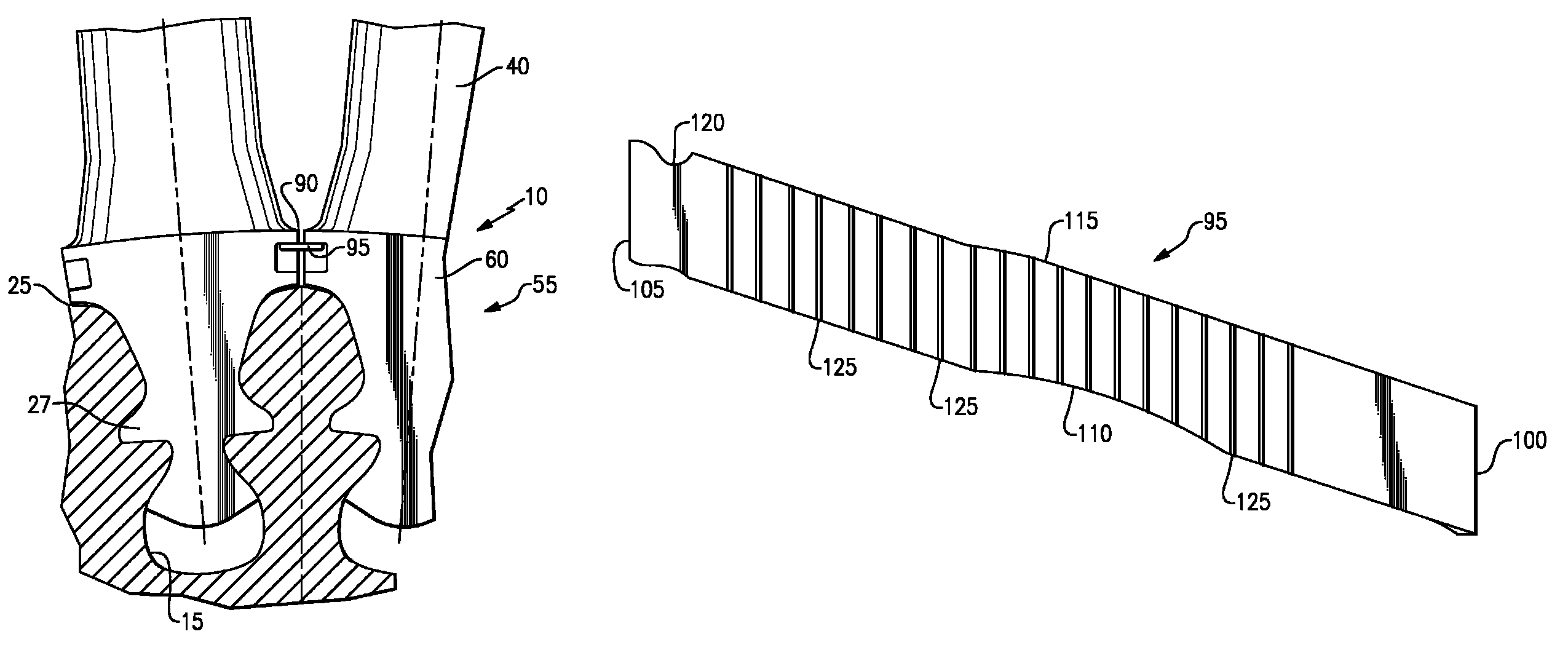
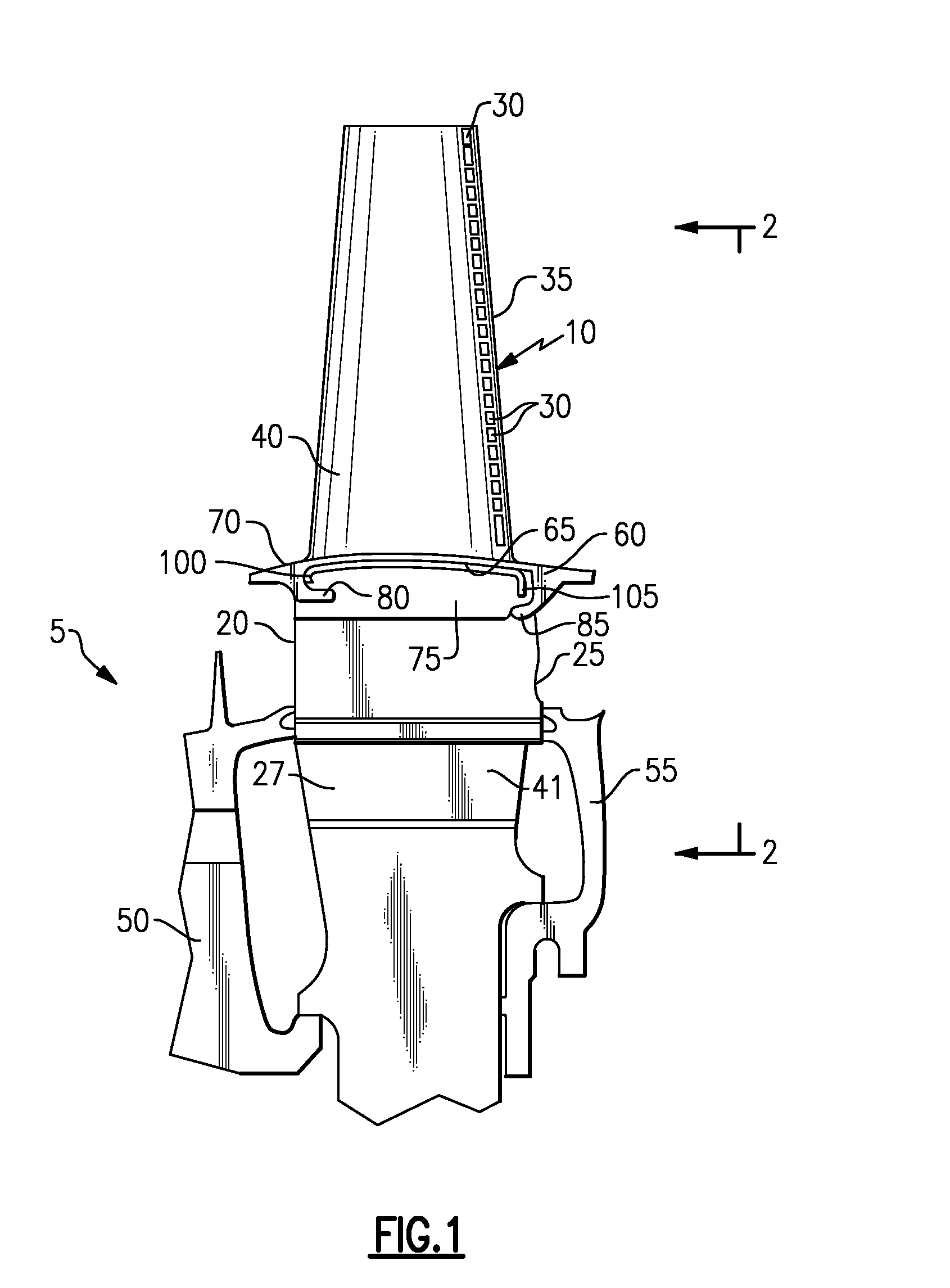
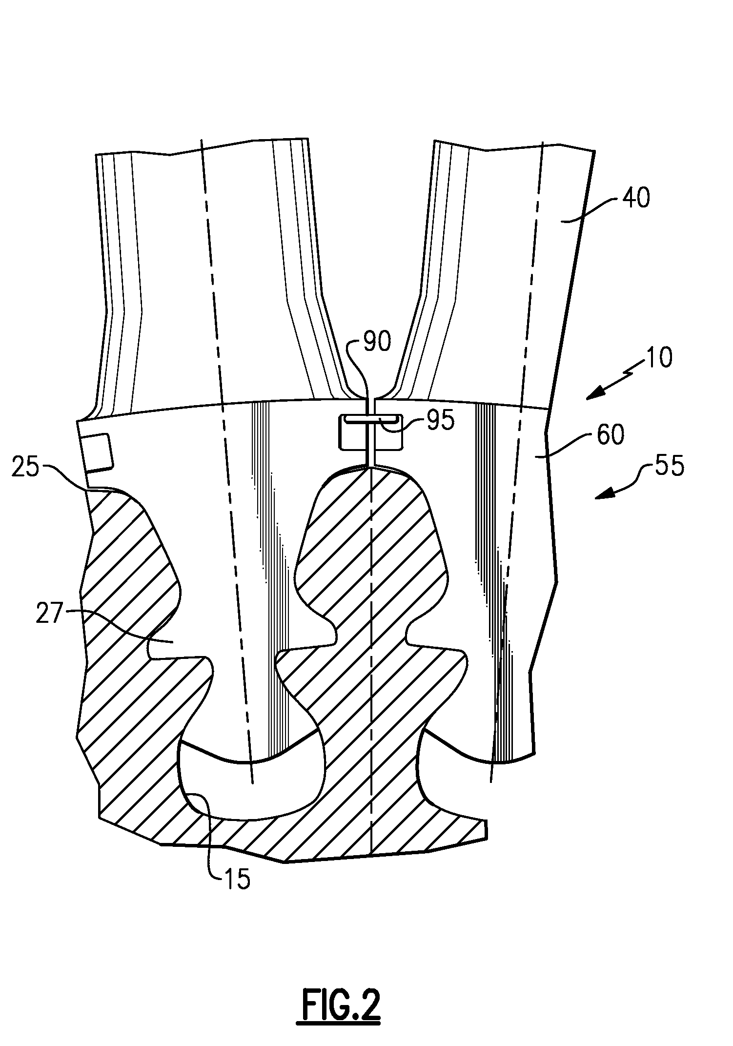
[0018]Referring to the drawing and particularly to FIGS. 1 and 2 thereof, the present invention is utilized on a single stage turbine typically a high-pressure turbine of a modern gas turbine engine. The turbine rotor generally illustrated by reference number 5 is comprised of a plurality of circumferentially spaced turbine blades 10 suitably mounted in broach slots 15 formed in the rim 20 of a turbine disk 25. Preferably, the mounting of the blades to the disk is by the well-known broached-fir tree attachment at the blade's root portion 27. The blades are internally air cooled from compressor discharge air that is fed to the blade from the space between the blade and the rim of the disk by any well-known distribution system (not shown). As is well known in the art, a plurality of radially spaced apertures 30 extending adjacent to the trailing edge 35 of airfoil portion 40 of blade 10 discharges the cooling air from cooling passages internally of the blade (not shown) into the engin...


PUM


Abstract

Convective cooling of gas turbine engine airfoil platforms is enhanced by grooving the interface of the platforms with corresponding platform-to-platform seals, thereby accelerating cooling airflow over the platform surfaces.

Description

[0001]The U.S. Government has a paid-up license in this invention and the right in limited circumstances to require the patent owner to license others on reasonable terms as provided for by the terms of Contract No. N00019-02-C-3003 awarded by the Department of the Navy.BACKGROUND OF THE INVENTION[0002]1. Technical Field[0003]This invention relates generally to aircraft gas turbine engines and particularly to the cooling of the platform sections of turbine airfoils employed in such engines.[0004]2. Background Art[0005]The operation of gas turbine engines is well known. Such engines include a serial arrangement of a fan, a compressor, a combustor and a turbine. Air admitted into the inlet of the engine is compressed by the engine's compressor. The compressed air is then mixed with fuel in the engine's combustor and burned. The high-energy products of combustion of the burned air-fuel mixture then enter the turbine which extracts energy from the mixture in order to drive the compresso...

Claims


Application Information

Patent Timeline
Patent Type & Authority Patents(United States)
IPC IPC(8): F01D25/12
CPCF01D5/081F01D5/187F01D11/008F05D2240/57F05D2240/81Y02T50/676Y02T50/60
Inventor SPANGLER, BRANDON W.PAAUWE, CORNEIL S.LEHANE, CHRISTOPHER J.TRACY, ANITA L.WIEDEMER, JOHN D.HJELM, SCOTT D.
Owner RTX CORP
Why Eureka
Try Eureka