Method for controlling the hybrid drive of a motor vehicle and control system

a hybrid drive and control system technology, applied in the direction of analogue computers, electric energy vehicles, internal combustion piston engines, etc., can solve the problems of not being able to achieve the adaptation to driving dynamics requirements with difficulty, and not being able to overcome branched logic with difficulty

Active Publication Date: 2012-08-21
MAGNA STEYR FAHRZEUGTECHN
View PDF19 Cites 22 Cited by
  • Summary
  • Abstract
  • Description
  • Claims
  • Application Information

AI Technical Summary

Benefits of technology

[0028]The control system is composed of a series of modules which, in a program controller, are imaginary units in the program sequence, which units themselves again comprise individual blocks (which are assigned boxes in the figures). The particular configuration, function and arrangement of the modules and blocks enable the execution of the method according to the invention. The manner in which and the effect with which this takes place can be gathered from the description of the system on the basis of an exemplary embodiment.

Problems solved by technology

For this reason alone, it is not possible for the capacities of all the components to be optimally utilized at the same time and for said components to also be operated at their most economical operating points at which they are subjected to the least wear.
With a branched logic of said type, an adaptation to driving dynamics requirements can only be obtained with difficulty.
This is particularly disadvantageous if a limitation of wheel slip is desired or even, in a vehicle with two driven axles, the distribution of the torque between the two axles is to be controlled.
A further problem with heavily branched logic which can only be overcome with difficulty is the transition from one mode to another.
In said document, an “efficiency optimizing” mode is also provided, but said mode optimizes not the efficiency of the entire arrangement but rather only the efficiency of the internal combustion engine; the efficiencies and restrictions of the other components remain unconsidered.

Method used


Image

  • Method for controlling the hybrid drive of a motor vehicle and control system
  • Method for controlling the hybrid drive of a motor vehicle and control system
  • Method for controlling the hybrid drive of a motor vehicle and control system

Examples


Embodiment Construction

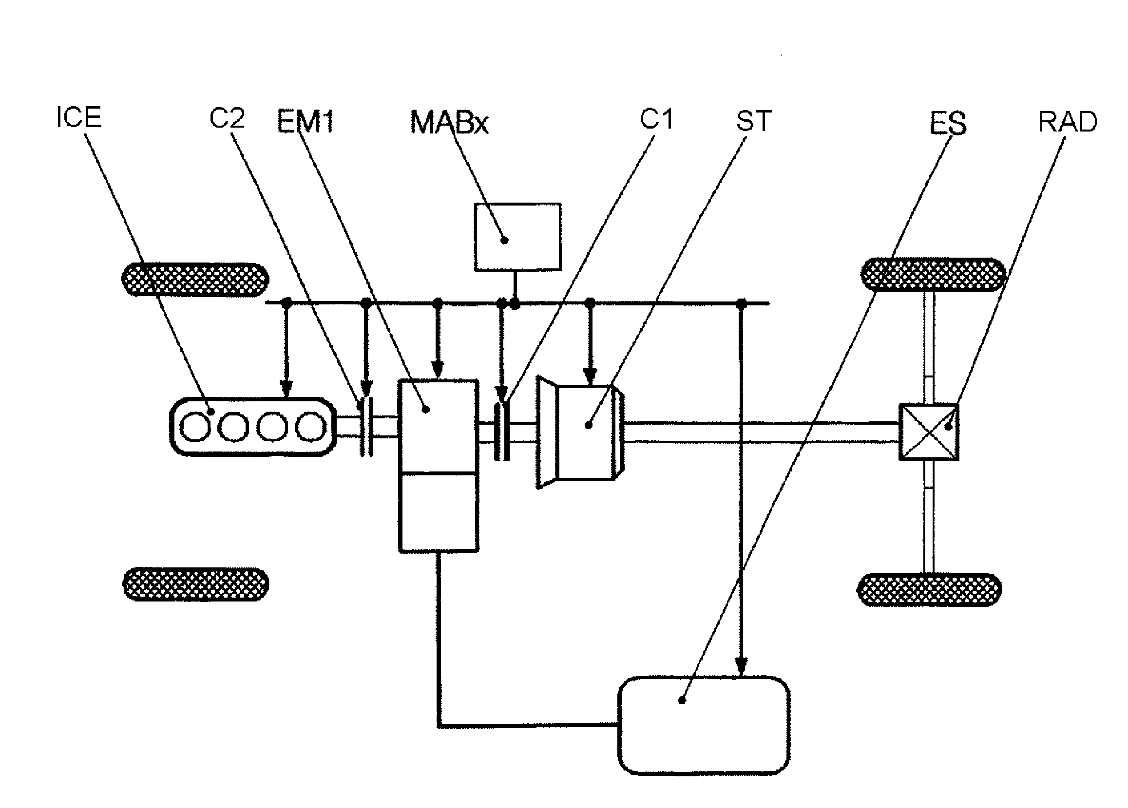
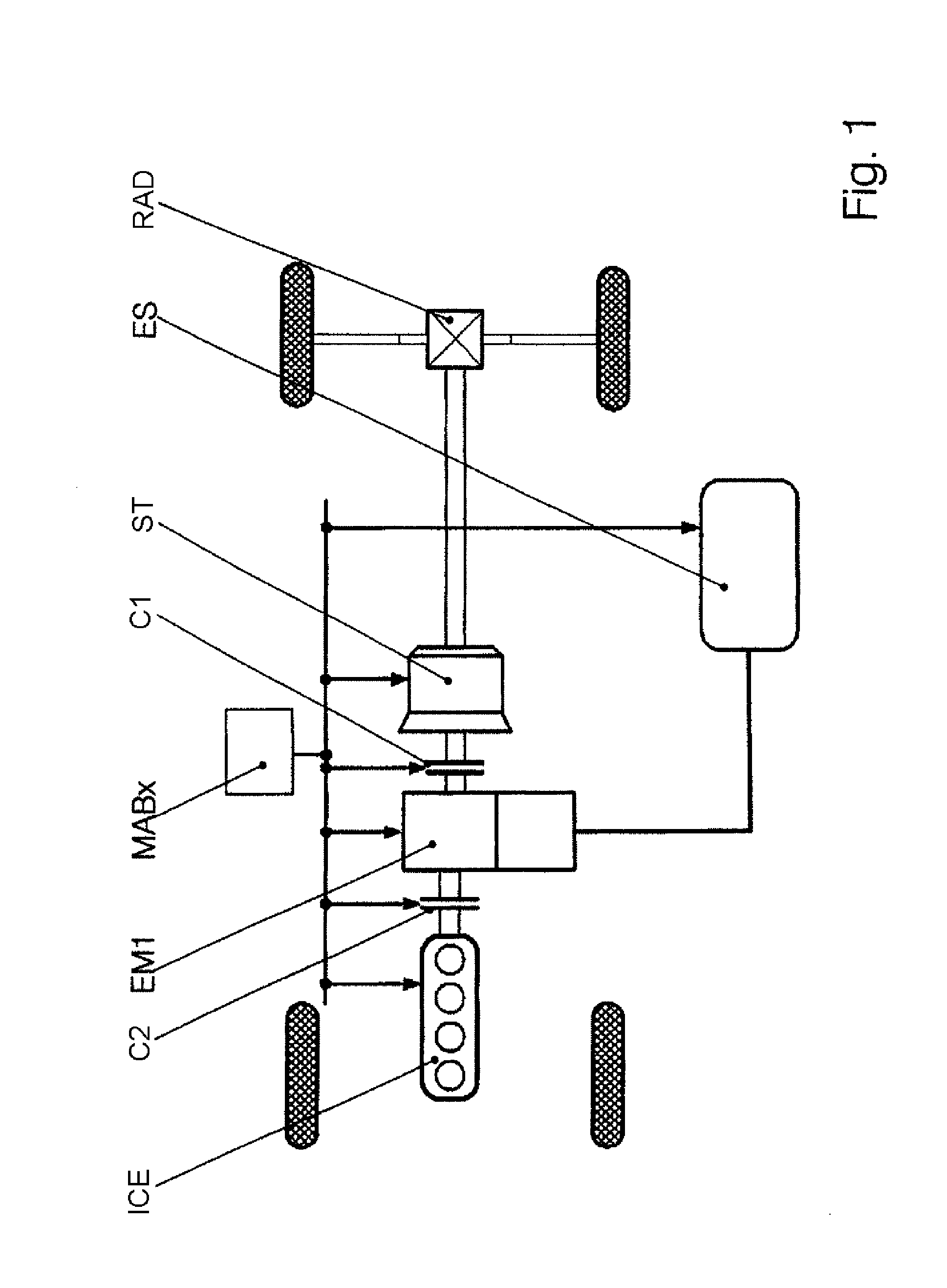
[0051]A simple hybrid drive that can be controlled using the method according to the invention, as per FIG. 1, is composed of the following components: an internal combustion engine ICE, an electric machine EM1, a shift transmission ST or a transmission with a fixed step-down transmission ratio, a rear axle differential RAD and an energy store ES—a high-capacity high-voltage battery, referred to simply as a battery below, or the like, and also a first clutch C1 between the electric machine EM1 and the shift transmission ST, and a second clutch C2 between the internal combustion engine ICE and the electric machine EM1. A control unit (MABx) is connected to the components by means of lines that are not shown in detail in FIG. 1. The internal combustion engine ICE and the electric machine EM1 are summarized below under the term “machines”.

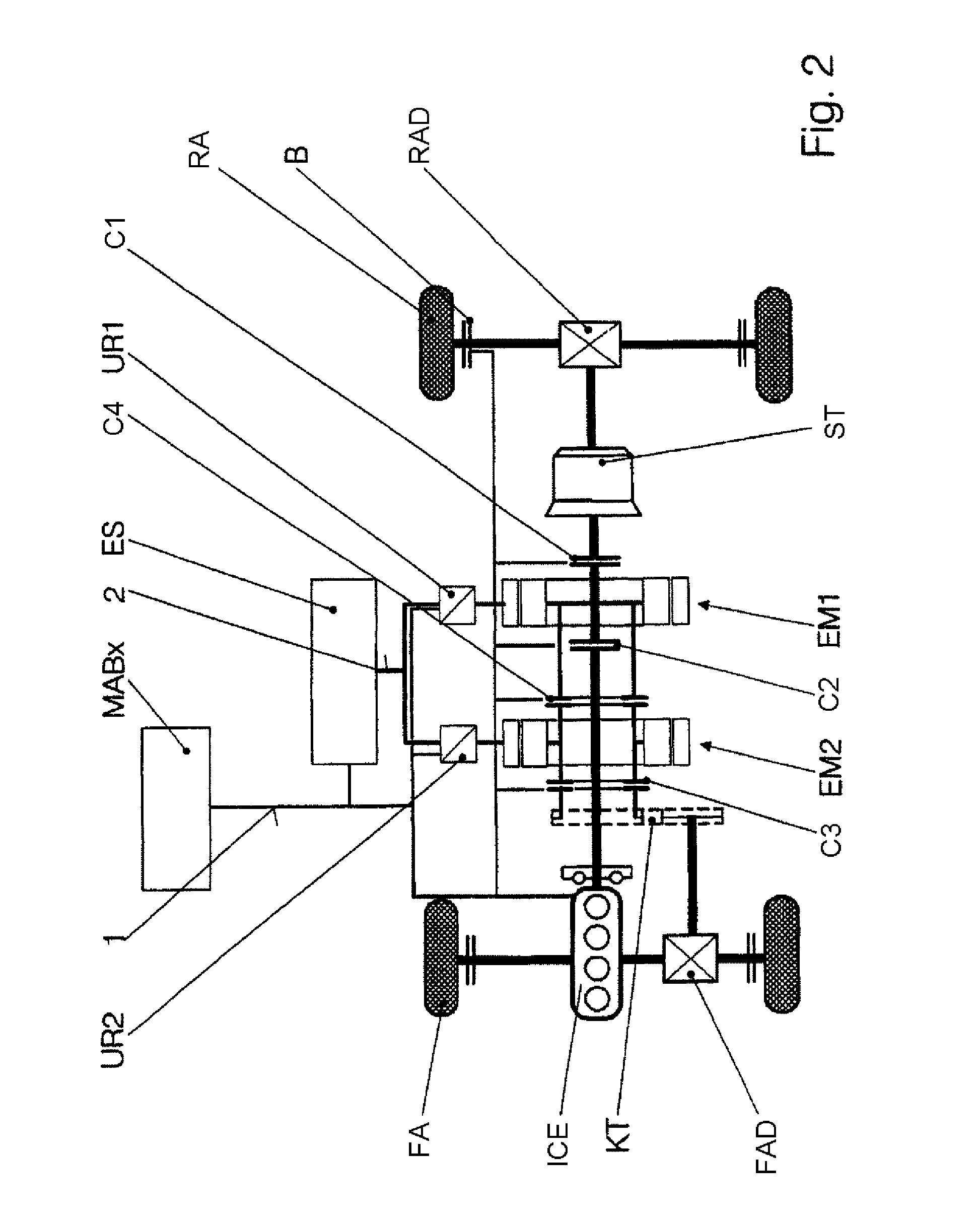
[0052]FIG. 2 shows a complex hybrid drive to which the exemplary embodiment described further below relates. Said hybrid drive is composed of the fol...


PUM


Abstract

A method and an apparatus for controlling the hybrid drive of a motor vehicle having the following components: internal combustion engine (VKM), manual transmission (SG), at least one electrical machine (Emi), at least one clutch (Kj) and an energy storage device (ES), and at least one driven axle (HA; VA) are intended to provide maximum efficiency and service life of the components. To this end, a decision is made about which operating modes (AMK) are possible on the basis of a driver input (FW) and operating state, a division is made about which gears (Gj) are available for the possible operating modes (AMK), so that a larger number of modes (AMGK) are available for selection, operating points which correspond to the driver input are determined for all these modes (AMGK), taking into account the operating state and system state (SZA), the modes (AMGK) are assessed and the mode (AMGK*) which is assessed as being most expedient is selected.

Description

BACKGROUND OF THE INVENTION[0001]The invention relates to a method for controlling the hybrid drive of a motor vehicle, which hybrid drive comprises the following components: an internal combustion engine, an axle drive transmission, at least one electric machine, at least one clutch, at least one energy store, and at least one driven axle. In the simplest case, the hybrid drive to be controlled is composed of an internal combustion engine, an electric machine that is arranged in series and that can be operated as a motor and as a generator, a single-stage (that is to say non-shiftable) step-down transmission and differential, as an axle drive transmission, for a driven axle. The hybrid drive to be controlled may however also comprise a plurality of electric machines in a more complex arrangement, a plurality of clutches and a plurality of—in particular two—driven axles.[0002]In known controllers, the driver demand and capacities of the torque sources and sinks (this means the elect...

Claims


Application Information

Patent Timeline
Patent Type & Authority Patents(United States)
IPC IPC(8): G06F17/00B60W10/10B60W10/12B60W30/18
CPCB60K6/445B60K6/52B60K6/54B60W10/02B60W10/06B60W10/08B60W10/11B60W10/14B60W10/16B60W10/26B60W30/188B60W20/102B60L11/12B60L11/14B60L15/2045B60L15/2054B60K6/48Y10T477/23B60L2240/445B60W20/00B60W2510/0676B60W2510/244B60W2510/246B60W2520/28B60W2540/10B60W2540/12Y02T10/56Y02T10/6221Y02T10/6239Y02T10/6265Y02T10/6286B60L2250/20Y02T10/7077Y02T10/7283Y10T477/26B60W20/11Y02T10/72Y02T10/84B60L50/16Y02T10/40Y02T10/62Y02T10/64Y02T10/7072Y02T10/70
Inventor MORI, PETERSCHOBERL, THEODORMARTIN, HELMUTKRAMER, FLORIANBUROW, CLEMENSHEIN, JAN-ERIKPOSCH, MANFRED
Owner MAGNA STEYR FAHRZEUGTECHN
Why Eureka
Try Eureka