Seal performance for hydrogen storage and supply systems

a technology of hydrogen storage and supply system, which is applied in the direction of piston rings, machines/engines, electrochemical machining apparatuses, etc., can solve the problems of promoting hydrogen gas leakage across, forming microscopic leak paths, and complex structural components, so as to reduce the surface roughness of the mating surface, controllable heating

Inactive Publication Date: 2012-08-28
GM GLOBAL TECH OPERATIONS LLC
View PDF34 Cites 40 Cited by
  • Summary
  • Abstract
  • Description
  • Claims
  • Application Information

AI Technical Summary

Benefits of technology

[0006]The spring-energized and plastic coated radial seal may be of any general construction appropriate for the particular sealing application being contemplated. The seal may generally include a relatively rigid plastic jacket that at least partially surrounds a spring or other load-exerting element. The plastic jacket may include a heel portion and pair of flexible sealing lips with an inner and outer surface. The inner surface of the sealing lips may at least partially define a groove for receiving the spring. A constant force supplied by the spring against the inner surface of the sealing lips may flex the sealing lips radially outwardly and bias the outer surface of the sealing lips against an adjacent mating surface and an oppositely adjacent seal gland surface. The gas pressure available to the seal may further increase this biasing force and thus, at higher gas pressures, promote tighter sealing engagement between the outer surface of the sealing lips and their adjacent surfaces. The plastic jacket may be constructed from relatively rigid plastic materials that include, but are not limited to, high performance polymers such as filled and non-filled polytetrafluoroethylene (PTFE) compounds and ultra-high molecular weight polyethylene (UHMW-PE).
[0008]The seal mating and seal gland surfaces should be provided with low surface roughness for optimal sealing engagement. These surfaces are generally metal surfaces which contact the plastic jacket of the seal to manage the flow and pressure of hydrogen gas. For example, industry recommendations generally state that the surface roughness should not exceed about 6 microinches for a dynamic mating surface and about 12 microinches for a static mating or seal gland surface when the media to be sealed is hydrogen gas. Seal mating or gland surfaces with a surface roughness that exceeds these recommendations tend to result in the formation of microscopic leak paths. This is because the seal is unable to sufficiently compliment the larger inter-asperity voids on the mating or gland surface through which hydrogen gas can likely pervade. Rougher dynamic mating surfaces can also expedite wearing of the seal surfaces and lead to a decrease in seal life and possibly a greater hydrogen leakage rate across the seal.
[0009]Several treatment procedures have thus been developed for treating at least the seal mating surface to provide it with a low surface roughness finish that can better accommodate the outer surfaces of the plastic jacket's sealing lips. These procedures help provide smoother surfaces than standard mechanical polishing techniques such as grinding and buffing. The ability to further reduce the surface roughness of a seal mating surface can, in turn, facilitate a better seal between the mating surface and the outer surfaces of the sealing lips, decrease hydrogen leakage across the seal, reduce wear of the outer plastic seal surfaces, and improve the reliability of hydrogen gas pressure management in hydrogen storage and supply systems.
[0012]A chemical polishing technique that may be utilized is isotropic finishing. This technique is known to skilled artisans and generally involves submerging the part that includes the seal mating surface into a suitable isotropic chemical bath that is being agitated. The isotropic chemical bath generally comprises an acidic medium and an appropriate supply of abrading elements. The composition of the isotropic chemical bath and the constant agitation progressively erode the surface asperities on the mating surface and thus significantly reduce its surface roughness on a microscopic scale. Afterwards, the mating surface may be submerged in a burnishing liquid bath that is agitated similarly to the isotropic chemical bath. The burnishing liquid bath generally comprises a basic medium that neutralizes any remaining isotropic chemical residue on the mating surface.
[0013]An electrochemical polishing technique that may be utilized is electropolishing. This technique—also sometimes referred to as “reverse plating”—is known to skilled artisans and generally involves forming an electrochemical cell where the part that includes the seal mating surface is submerged into an electropolishing bath as the anode (positive terminal). Other metal substrates are likewise submerged as the cathode (negative terminal). The electropolishing bath, which may comprise an electrolytic solution, may be controllably heated if desired. An electric current is then applied to the electrodes from an appropriate power source. Such an electrochemical cell progressively removes surface material from the seal mating surface—more so at the peaks of the surface asperities—by way of anodic dissolution. The surface roughness of the mating surface is thus significantly reduced and deburred as a result.

Problems solved by technology

While these and other similar components can range from simple to very complicated in terms of structural complexity, they are oftentimes shaped at some point for axial flow of hydrogen gas and therefore may contain generally round interior surfaces that need to be sealed.
The highly diffusive nature of hydrogen gas as well as its cold operating temperatures can, however, promote hydrogen gas leakage across the seals located in these axial flow areas.
Seal mating or gland surfaces with a surface roughness that exceeds these recommendations tend to result in the formation of microscopic leak paths.
This is because the seal is unable to sufficiently compliment the larger inter-asperity voids on the mating or gland surface through which hydrogen gas can likely pervade.
Rougher dynamic mating surfaces can also expedite wearing of the seal surfaces and lead to a decrease in seal life and possibly a greater hydrogen leakage rate across the seal.

Method used


Image

  • Seal performance for hydrogen storage and supply systems
  • Seal performance for hydrogen storage and supply systems
  • Seal performance for hydrogen storage and supply systems

Examples


Embodiment Construction

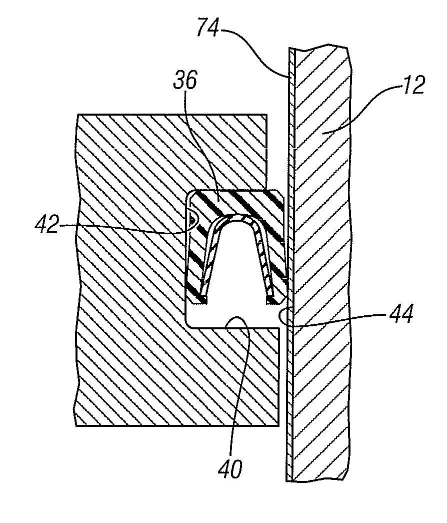
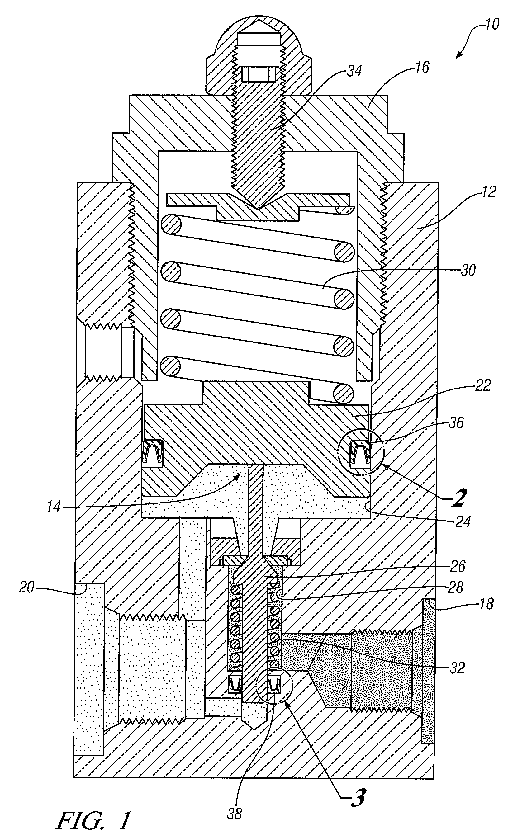
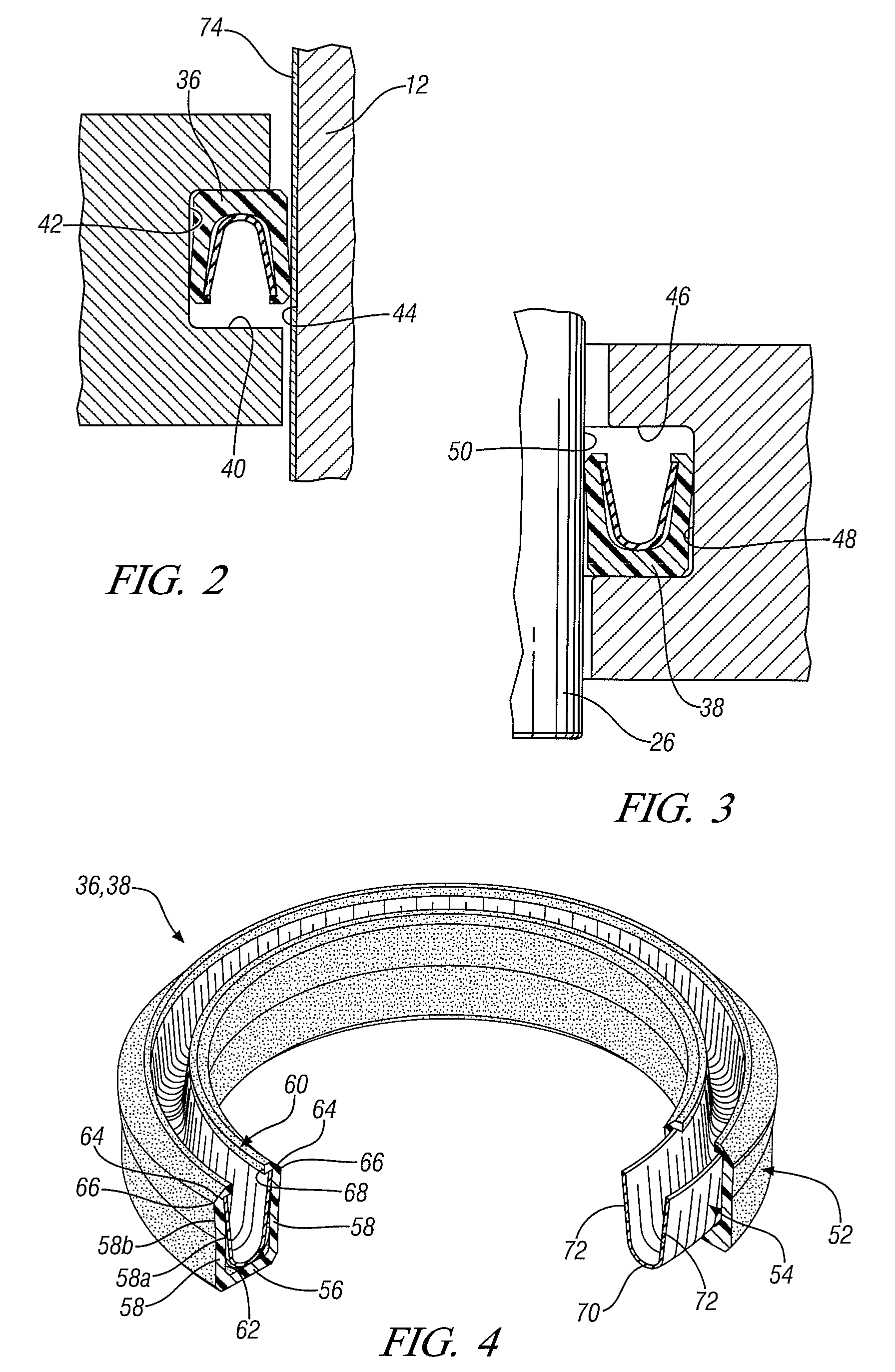
[0019]The performance and durability of static and dynamic seals within hydrogen storage and supply systems can be improved using a spring-energized and plastic coated radial seal that engages a mating surface that has been treated by at least one of a variety of procedures. These treatment procedures include applying a hard, low-friction and hydrogen impervious layer to the seal mating surface, isotropic finishing, and electropolishing. The combination of this seal construction and the treatment of the seal mating surface helps reduce hydrogen leakage at the interface of the seal and the mating surface, and also helps reduce the onset of seal surface abrasions and wear particularly when the use of lubricants is prohibited. While the following discussion focuses primarily on treating seal mating surfaces, it is to be understood that other seal engaging surfaces—most notably seal gland surfaces—may also be treated with the disclosed treatment procedures to achieve similar results.

[00...


PUM

PropertyMeasurementUnit
temperaturesaaaaaaaaaa
pressuresaaaaaaaaaa

Abstract

The performance and durability of static and dynamic seals for hydrogen storage and supply systems has been improved by utilizing a spring-energized and plastic coated radial seal in combination with at least a mating surface that has been treated by one of a variety of procedures. These procedures include applying to the mating surface a low-friction, hard, and hydrogen impervious coating, chemically polishing the mating surface, and electrochemically polishing the mating surface. Each of these procedures significantly reduces, on a microscopic scale, the surface roughness of the mating surface. The seal can thus form a tighter and more gas-tight seal with the smoother mating surface so as to decrease the loss of hydrogen gas across the seal. The smoother mating surface can also improve seal life by reducing seal surface wear.

Description

TECHNICAL FIELD[0001]This invention pertains to the improved performance of static and dynamic seals in hydrogen storage and supply systems. More specifically, a spring-energized plastic seal may be sealingly engaged against at least an adjacent mating surface that has been treated to better accommodate the seal's contacting surface. The mating surface may be treated by applying a low-friction, hard, and hydrogen impervious coating thereto. The mating surface may also be treated by chemical or electrochemical polishing.BACKGROUND OF THE INVENTION[0002]Fuel cell technology has become a viable option for the automotive industry to generate power for vehicle operation. Certain types of fuel cells, such as proton exchange fuel cells (PEM fuel cells), generate electricity by delivering a flow of hydrogen gas to the anode side of a membrane-electrode-assembly and a flow of oxygen gas to the cathode side. A proton-conducting electrolyte sandwiched between the anode and cathode facilitates ...

Claims


Application Information

Patent Timeline
Patent Type & Authority Patents(United States)
IPC IPC(8): F16J15/12F16J15/32
CPCF16J15/3236H01M8/04089H01M8/04201Y02E60/34Y02E60/50
Inventor LEV, LEONID C.PODORASHI, DIMITRI A.LUKITSCH, MICHAEL J.MICHLER, THORSTENXIAO, XINGCHENG
Owner GM GLOBAL TECH OPERATIONS LLC
Why Eureka
Try Eureka