Charged particle beam irradiation system and charged particle beam extraction method

a charge beam and irradiation system technology, applied in the field of charge particle beam irradiation system and charged particle beam extraction method, can solve the problems of reducing the efficiency of beam use, unable to effectively fire the charge accumulated in the synchrotron, etc., and achieves the effect of ensuring the uniformity of irradiation dose, ensuring accuracy, and efficient extraction and us

Active Publication Date: 2012-08-28
HITACHI LTD
View PDF20 Cites 9 Cited by
  • Summary
  • Abstract
  • Description
  • Claims
  • Application Information

AI Technical Summary

Benefits of technology

[0017]In the wobbler method, a scatterer is irradiated with a circularly scanning beam to form the SOBP adapted to the affected part. At this time, a beam irradiation start point must coincide with an end point to ensure uniformity of the irradiation dose. Further, when the change with time in the current intensity of the circularly scanning beam fluctuates, uneven uniformity results in the irradiation dose on a plane of an irradiation field. Specifically, uniformity of the irradiation dose can be ensured by making the beam circular scanning cycle coincide with the beam extraction cycle in the extraction control period of the synchrotron.
[0034]Further, in accordance with the aspects of the present invention, the control of the amplitude of the extraction radiofrequency voltage can be performed more accurately, and the control of the intensity of the ion beam irradiated on the object can be performed accurately.

Problems solved by technology

The narrower the desired SOBP width, the lower the beam use efficiency, so that the accumulated charge of ion beams in the synchrotron cannot be fired effectively.
The RMW irradiation method does not therefore allow the beam use efficiency to be enhanced by simply controlling the amplitude of the extraction radiofrequency voltage according to the accumulated beam charge amount before the start of the extraction control.

Method used


Image

  • Charged particle beam irradiation system and charged particle beam extraction method
  • Charged particle beam irradiation system and charged particle beam extraction method
  • Charged particle beam irradiation system and charged particle beam extraction method

Examples


first embodiment

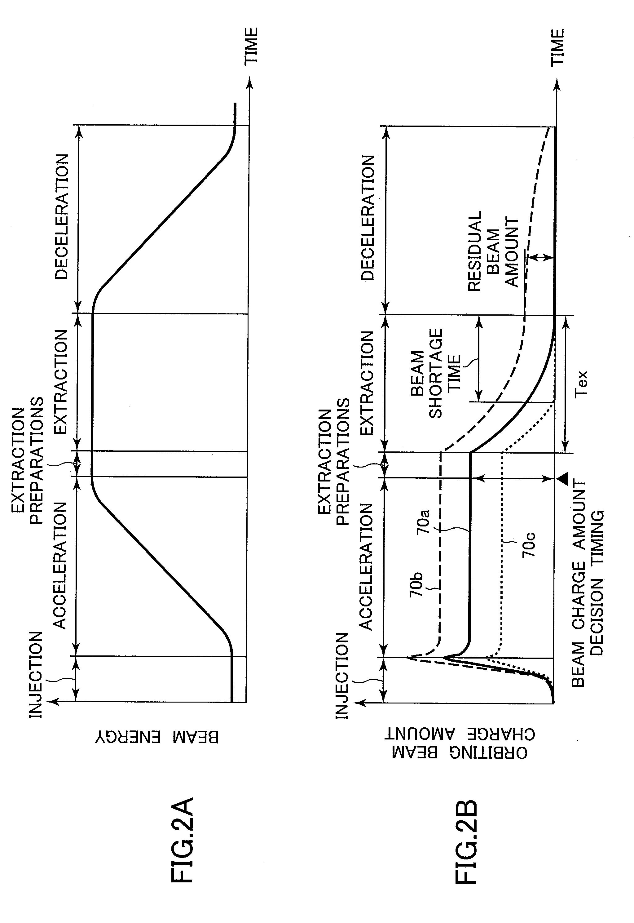
[0048]A charged particle beam irradiation system and a charged particle beam extraction method according to a first preferred embodiment of the present invention will be described below with reference to FIGS. 1 and 2A and 2B. Note that the charged particle beam irradiation system and the charged particle beam extraction method according to the first embodiment of the present invention are concerned mainly with an ion beam among charged particle beams. Throughout this specification, therefore, the term “beam” represents the “ion beam”.

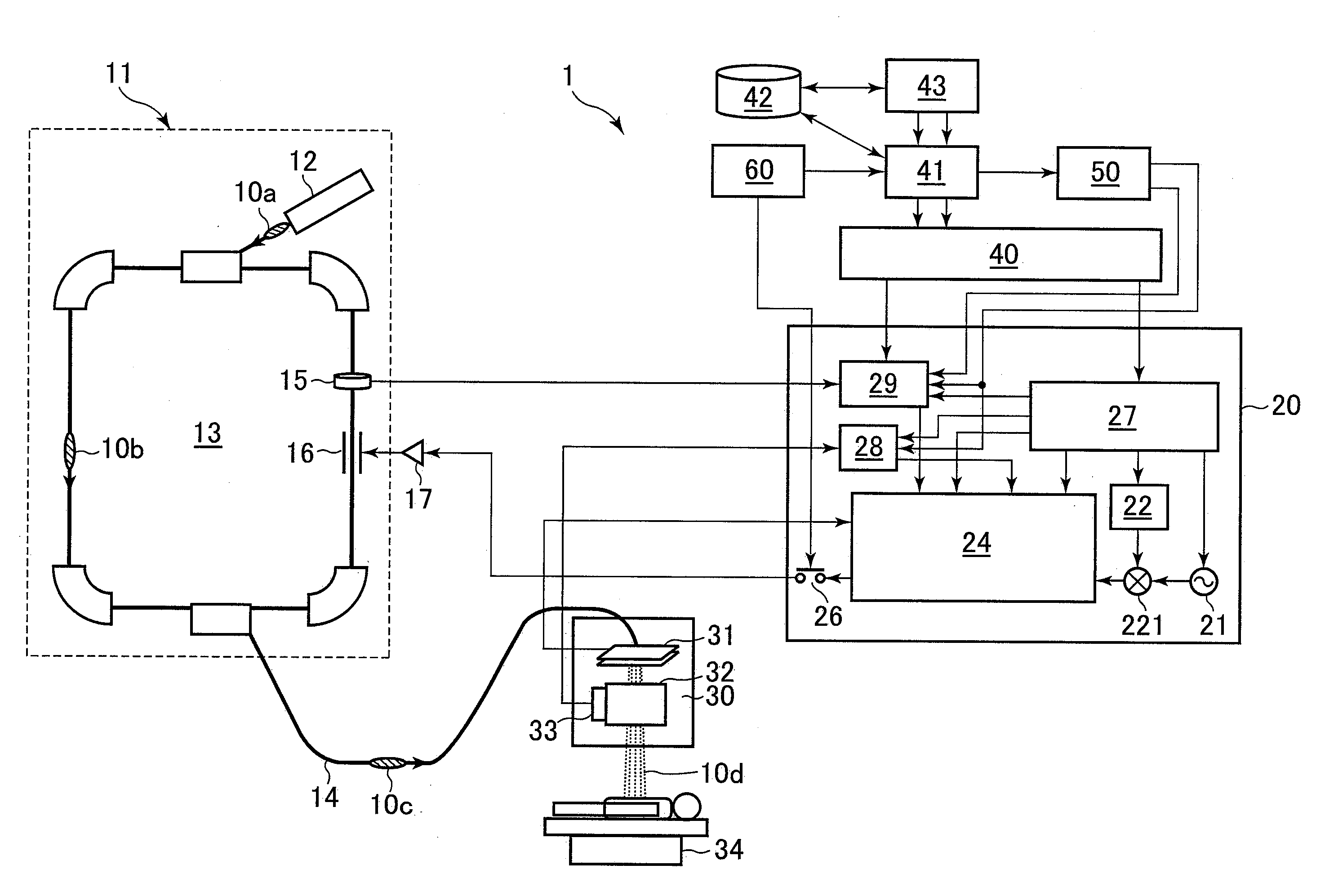
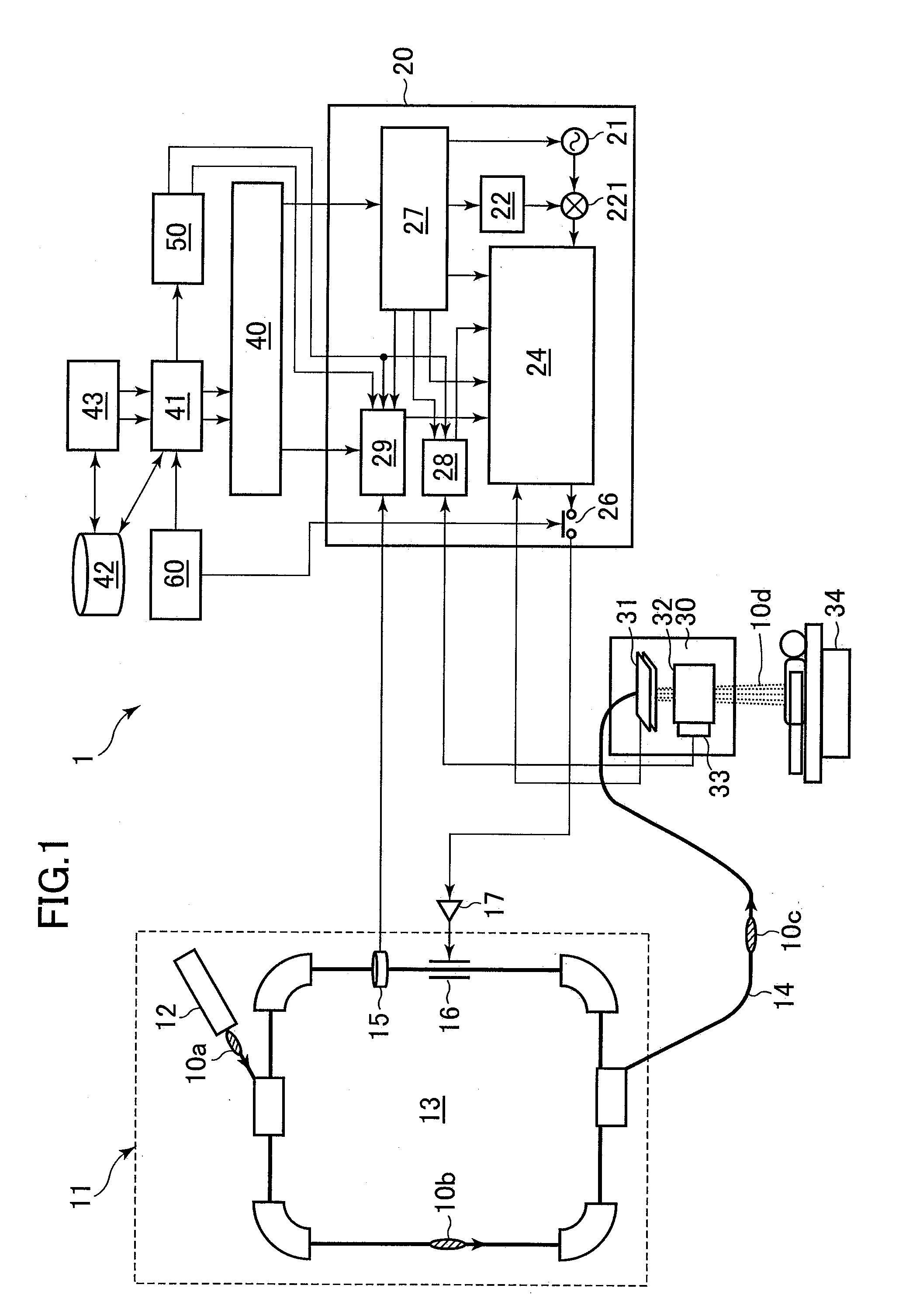
[0049]Referring to FIG. 1, a charged particle beam irradiation system 1 according to the first embodiment of the present invention includes an ion beam generator 11, a beam transport apparatus 14, and an irradiation field formation apparatus (ion beam irradiation apparatus; hereinafter referred to as the irradiation apparatus) 30. The beam transport apparatus 14 provides communication between the ion beam generator 11 and the irradiation apparatus 30 i...

second embodiment

[0104]A second embodiment of the present invention will be presented. In the second embodiment of the present invention, the wobbler method is adopted for the beam irradiation method. Control of the beam extraction control signal is necessary in time with the scanning cycle of wobbler scanning magnets, while adjusting the extracted beam current intensity to a constant value. Arrangements other than the foregoing are the same as those of the first embodiment shown in FIG. 1. FIGS. 8(a) to 8(e) are graphs showing changes in a scanning magnet excitation current and changes in the accumulated beam charge amount and the dose monitor detection signal when the target value for the extracted beam current intensity is controlled with changing amounts of accumulated charge of ion beams. FIG. 9 is a diagram showing an arrangement of an extraction controller in the second embodiment in which the present invention is applied to the wobbler method.

[0105]The wobbler method uses one set of two wobb...

third embodiment

[0108]A third embodiment of the present invention will be presented. The third embodiment of the present invention incorporates the raster beam scanning method for the beam irradiation method, and control for scanning while adjusting the extracted beam current intensity to a constant value is necessary. For the third embodiment of the present invention, a control method will be described, in which no gate control is performed during the beam extraction control. Other arrangements are the same those of the first embodiment of the present invention shown in FIG. 1. FIGS. 10(a) to 10(f) are graphs showing changes in the scanning magnet excitation current and changes in the accumulated beam charge amount and the dose monitor detection signal when the target value for the extracted beam current intensity is controlled with changing amounts of accumulated charge of ion beams, in which the present invention is applied to the raster beam scanning method. FIG. 11 is a diagram showing an arra...


PUM


Abstract

A charged particle beam irradiation system includes a synchrotron which accelerates an ion beam, an irradiation apparatus for irradiating an object with the ion beam introduced from the synchrotron, detection means for measuring an amount of accumulated charge of the ion beam that orbits in the synchrotron immediately before an extraction control period in an operating cycle of the synchrotron, and beam extraction control means for controlling extraction of the ion beam based on the measurement result of the accumulated beam charge amount so that extraction of a total amount of the ion beam is to be completed with an expiration of an extraction control time, the extraction control time representing a length of the extraction control period of the synchrotron and being set in advance.

Description

BACKGROUND OF THE INVENTION[0001]1. Field of the Invention[0002]The present invention relates to a charged particle beam irradiation system and charged particle beam extraction method. More particularly, the present invention relates to a charged particle beam irradiation system and a charged particle beam extraction method that are ideally adaptable to a particle therapy system that treats a cancer by irradiating an affected part (an object to be irradiated) with a charged particle beam (ion beam) such as a proton or a heavy ion.[0003]2. Description of the Related Art[0004]A particle therapy method is known as a radiation therapy for cancers, in which a cancer affected part of a patient is irradiated with an ion beam such as, for example, a proton or heavy ion beam. A particle therapy system used in such a therapy may include an ion beam generator, a beam transport line, and an irradiation apparatus. The ion beam generator includes a synchrotron or a cyclotron that accelerates the ...

Claims


Application Information

Patent Timeline
Patent Type & Authority Patents(United States)
IPC IPC(8): G21K5/04
CPCA61N5/10H05H7/10H05H13/04A61N2005/1087
Inventor NISHIUCHI, HIDEAKISAITO, KAZUYOSHITADOKORO, MASAHIROAKIYAMA, HIROSHIHIRAMOTO, KAZUO
Owner HITACHI LTD
Why Eureka
Try Eureka