Direct touch type metal diaphragm valve

a metal diaphragm valve, direct touch technology, applied in the direction of diaphragm valves, engine diaphragms, operating means/releasing devices of valves, etc., can solve the problems of metal diaphragm cracks, metal diaphragms that need to be replaced more frequently, and the elastic deformation volume of metal diaphragms has its own limitation, so as to achieve a more stable flow rate coefficient and reduce the change with time of valve sea

Active Publication Date: 2012-09-04
FUJIKIN INC
View PDF25 Cites 29 Cited by
  • Summary
  • Abstract
  • Description
  • Claims
  • Application Information

AI Technical Summary

Benefits of technology

[0027]With the present invention, a direct touch type metal diaphragm valve is made so that the maximum bulge height Δh of the metal diaphragm is 55 to 70% of the size (distance) of the maximum bulge height Δh, which is the minimum requirement to obtain a desired flow rate coefficient Cv without making it the full stroke ΔS of a valve, thus allowing distortion volume and distortion stress applied to the metal diaphragm during open / close operations of a valve to be smaller, and at the same time, a prescribed flow rate coefficient (Cv value) as required is fully secured. As a result, it is possible that the feasible number of repetitions of continuous open / close operations, which indicates the durability of the metal diaphragm valve, is raised to approximately 20 to 30 times that of the conventional metal diaphragm valve.
[0028]A stroke adjustment mechanism is provided according to the present invention, and approximately 3000 to 10000 continuous open / close operations are conducted before shipment of the valve in order to break-in the synthetic resin made valve seat in order to achieve its stabilization. As a result, the so-called changes with time of the valve seat are substantially reduced, thus the flow rate coefficient Cv (Cv value) is more stable.

Problems solved by technology

However, as stated above, the elastic deformation volume of the metal diaphragm has its own limitation.
With a conventional metal diaphragm valve of this type, there has been a problem that cracks are apt to be caused on a metal diaphragm.
When the number of repetitions of the open / close operation exceeds the above stated durability number, normally damage is caused due to the repetitions of displacement of the metal diaphragm 22, thus resulting in the need to replace the metal diaphragm valve more frequently.
Accordingly, various durability difficulties are encountered in practical use of continuous open / close operations with a conventional metal diaphragm valve (in the case of a 9.52 mmφ metal diaphragm 22 having an outside diameter of 26 mmφ, approximately 1.5 million times with a full stroke ΔS=1.2 mm, and approximately 2.5 million times with a full stroke ΔS=1.0 mm).
With this type of conventional diaphragm valve, there remains an unsolved problem that the Cv value is difficult to stabilize due to changes of flow rate characteristics over time, that is, the Cv value is easily affected by changes of the Cv value over time.
And, when open / close operations are conducted under conditions of high temperature, the flow rate at the time when the valve is fully open increases due to changes with time.

Method used


Image

  • Direct touch type metal diaphragm valve
  • Direct touch type metal diaphragm valve
  • Direct touch type metal diaphragm valve

Examples


embodiment 1

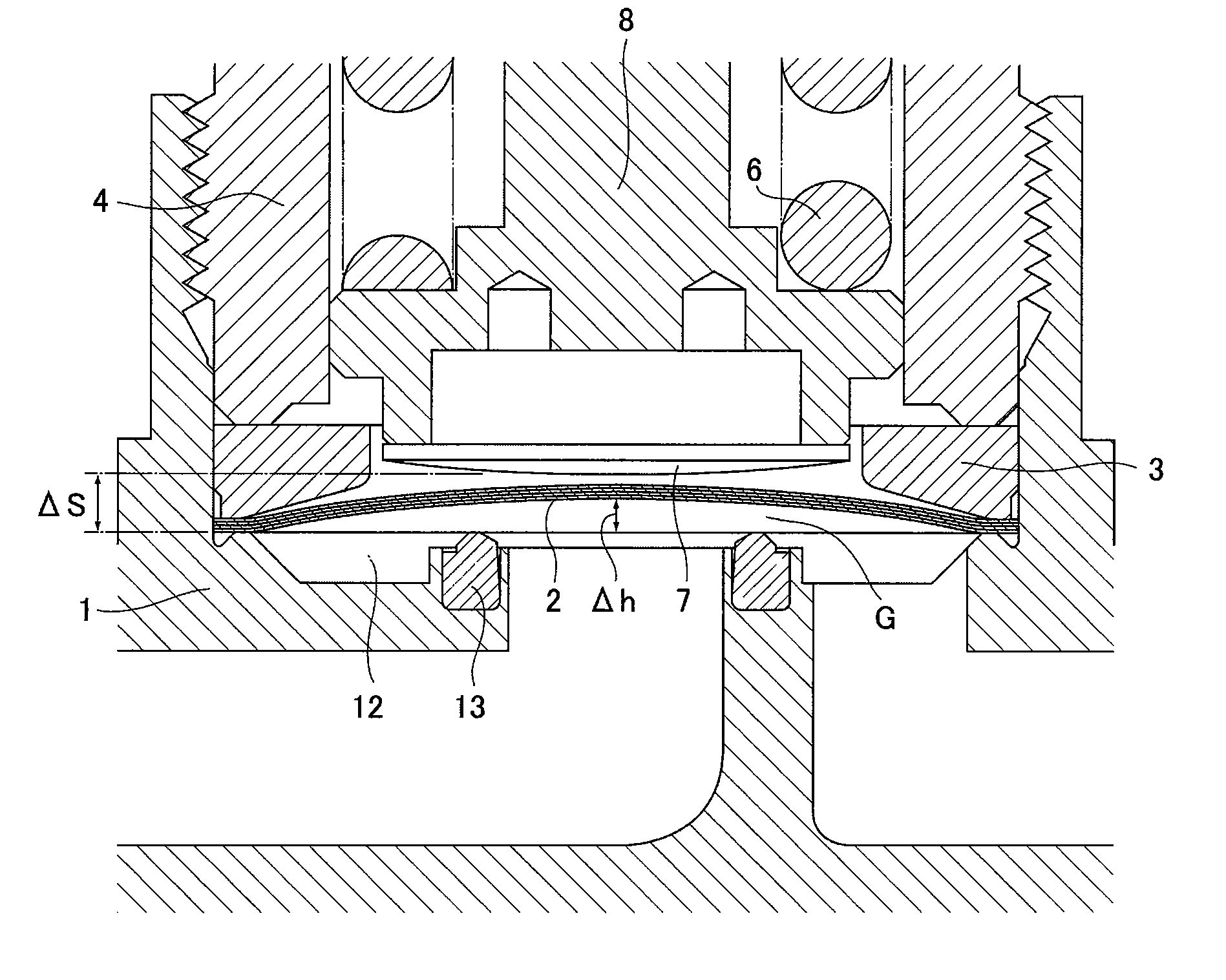
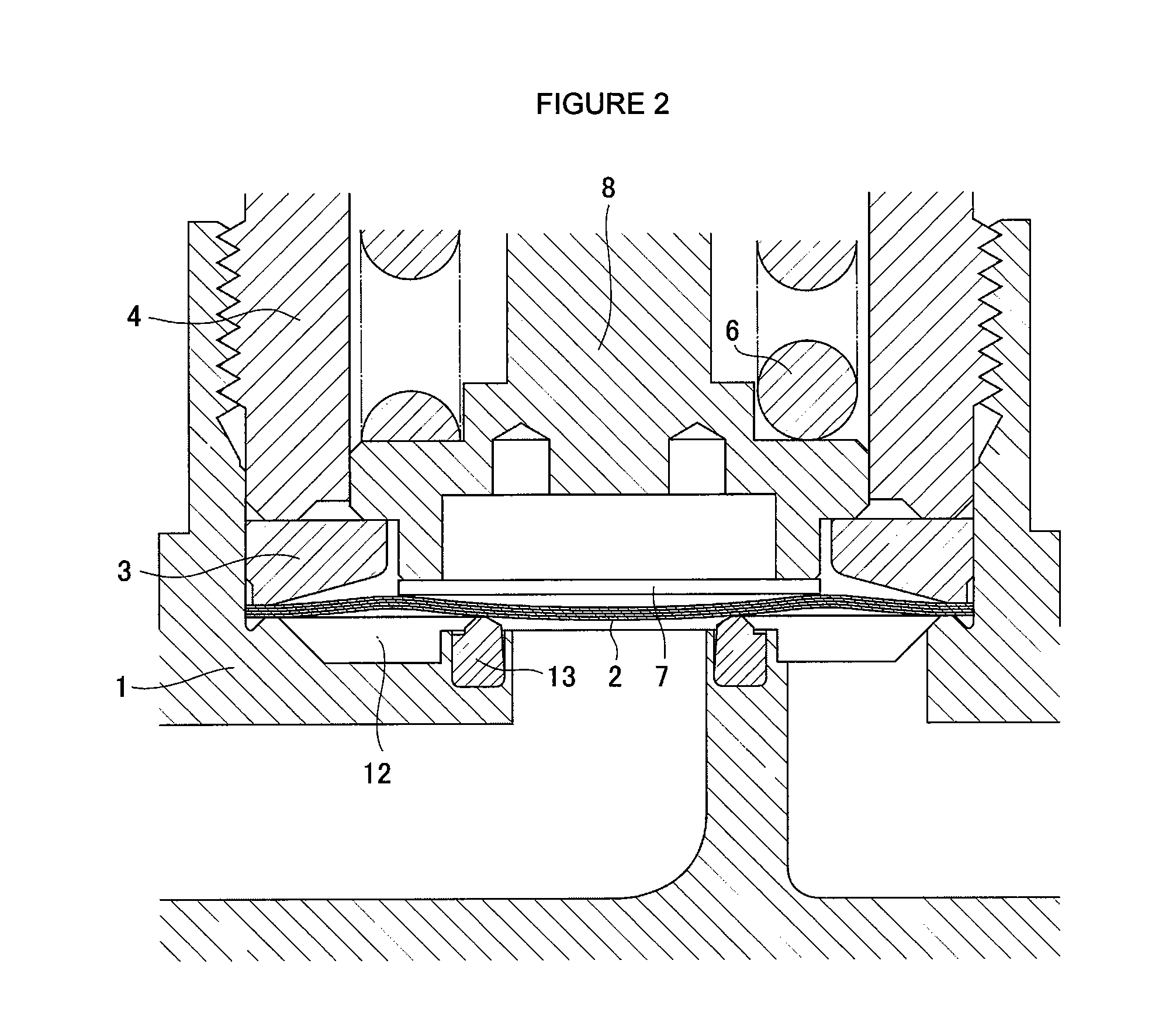
[0087]Referring to FIG. 2, FIG. 2 is a partially enlarged view to show the closed state of the valve for which the metal diaphragm 2 in the afore-mentioned implementation example 1 is used. FIG. 3 is a partially enlarged view to show the open state of the valve for which the metal diaphragm 2 in the afore-mentioned implementation example 1 is used. In accordance with FIG. 2 and FIG. 3, the valve stroke ΔS is chosen to be 1.5 mm. The metal diaphragm 2 is completely restored to its original shape due to the fact that the valve stroke ΔS is larger than the maximum height Δh=1.2 mm of a bulged part of the metal diaphragm 2.

embodiment 2

[0088]FIG. 4 and FIG. 5 are partly enlarged views to show a closed state (FIG. 4) and an open state (FIG. 5) when the valve stroke ΔS is made to be 0.7 mm in accordance with the valve shown in FIG. 1, in which the diaphragm 2 in the implementation example 1, mentioned above, is used. The metal diaphragm 2 remains slightly deformed without being restored completely back to its original state, as shown in FIG. 3, even when the valve is closed. Specifically, when the valve stroke ΔS is made to be small, deformation volume of the metal diaphragm 2 becomes small; hence, distortion stress applied to the metal diaphragm 2 becomes relatively small.

[0089]Now, when comparing a valve stroke ΔS=1.5 mm with a valve stroke ΔS=0.7 mm, much difference is seen in the shape of a metal diaphragm 2 as stated before, but it is learned that not much difference is seen in the space G between a valve seat 3 and the inner surface of a metal diaphragm 2.

embodiment 3

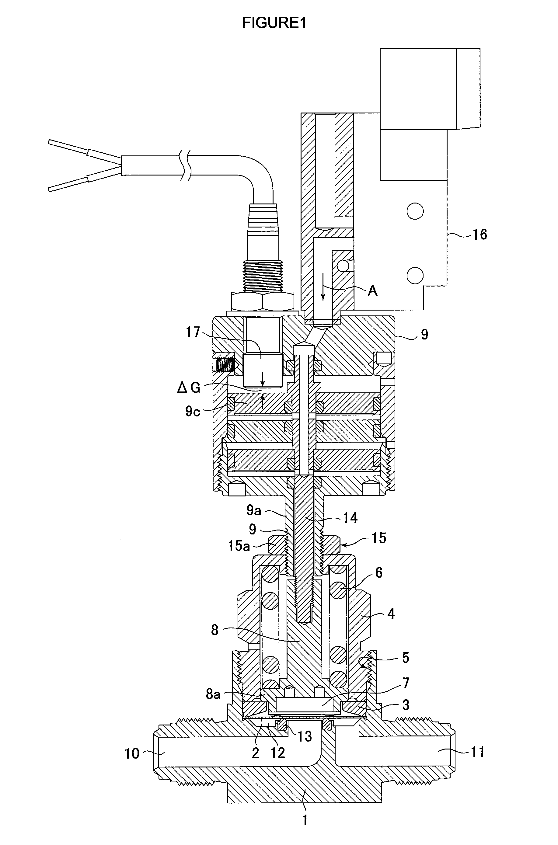
[0090]FIG. 6 and FIG. 7 show the results of a Cv value obtained by the afore-mentioned equation (2) after the flow rate was measured by using the afore-mentioned Cv value measurement test device, shown in FIG. 8, on the metal diaphragm shown in FIG. 1 wherein the metal diaphragm 2 in the afore-mentioned implementation example 1 is used. Table 1 is a chart to show the lift, flow rate and Cv value corresponding to this test. The test was conducted under conditions of operating air pressure of 0.55 Mpa, and the projected height of the valve seat of 0.128 mm (the height after baking at 80° C.).

[0091]

TABLE 1Lift (mm)Flow Rate (L / min)Cv Value0.000 0.00.0000.102 0.40.0030.20315.90.1300.31034.80.2840.40846.00.3750.50559.00.4820.59365.00.5310.70074.00.6040.79275.00.6120.89777.00.6281.00079.00.6451.10680.00.6531.20280.00.6531.31680.00.653

[0092]As apparent from FIG. 6 and FIG. 7, it is learned that a Cv value of 0.55 to 0.6 required for the valve can be achieved with a valve stroke ΔS of appro...


PUM

PropertyMeasurementUnit
outer diameteraaaaaaaaaa

Abstract

A direct touch type metal diaphragm valve, wherein durability of the valve, that is to say, the ensured number of continuous open / close operations of the valve, is substantially increased under conditions that an appropriate flow rate coefficient Cv is maintained, and changes of the afore-mentioned Cv value over time are mitigated by means of restricting the deformation of the valve seat over time. The afore-mentioned metal diaphragm is formed in a round, reverse-dish shape by laminating a plural number of thin stainless steel plates and a thin Nickel.Cobalt alloy plate, and its center part is bulged upward, and the maximum valve stroke of the valve is regulated to be 55% to 70% of the distance of the maximum bulge height Δh of the afore-mentioned metal diaphragm.

Description

[0001]This is a National Phase Application in the United States of International Patent Application No. PCT / JP2006 / 309369 filed May 10, 2006, which claims priority on Japanese Patent Application No. JP 2005-250300, filed Aug. 20, 2005. The entire disclosures of the above patent applications are hereby incorporated by reference.FIELD OF THE INVENTION[0002]The present invention relates to a direct touch type metal diaphragm valve such as is mainly used for gas supply systems and the like in semiconductor manufacturing facilities. The present invention also relates to a direct touch type metal diaphragm valve with high durability which makes it possible that the number of repetitions of the open / close operation of the valve is considerably increased, and that the variation of flow characteristics is reduced by means of stably maintaining a flow rate coefficient of the valve.BACKGROUND OF THE INVENTION[0003]A direct touch type metal diaphragm valve (hereinafter called a “metal diaphragm...

Claims


Application Information

Patent Timeline
Patent Type & Authority Patents(United States)
IPC IPC(8): F16K7/12
CPCF16J3/02F16K31/1226F16K31/1225F16K7/14F16K7/12
Inventor TANIKAWA, TSUYOSHIYAMAJI, MICHIOYAKUSHIJIN, TADAYUKIFUKUCHI, HIROSHI
Owner FUJIKIN INC
Why Eureka
Try Eureka