Powdered metal inlay

a technology of powdered metal and inlay, which is applied in the direction of liquid fuel engines, machines/engines, operating means/release devices of valves, etc., can solve the problems of limited longitudinal movement of tubular inlay preform within the tubular hull, and achieves high repeatability, reduce stress on the brazed bond, and preserve the hardness and wear resistance

Inactive Publication Date: 2012-09-11
NOVATECH HLDG CORP
View PDF24 Cites 7 Cited by
  • Summary
  • Abstract
  • Description
  • Claims
  • Application Information

AI Technical Summary

Benefits of technology

[0014]Differential coefficients of thermal expansion facilitate close approximation during cooling of a sintered cemented carbide tubular inlay preform (e.g., a first tubular portion) which is vacuum brazed within a corresponding tubular metal hull (e.g., a second tubular portion). Such a tubular inlay preform comprises at least one metal carbide and at least one nonvolatile cement which have previously been compressed and sintered in a predetermined shape. The tubular inlay preform's modulus of elasticity and thermal conductivity substantially exceed the corresponding parameters of the tubular metal hull, whereas the hull's coefficient of thermal expansion exceeds that of the preform. Longitudinal movement of a tubular inlay preform within a tubular hull may be limited by structural features of the hull and / or preform. Examples of such structural features include an inner surface lip extending inward from the hull's inner surface, and / or one or more frusto-conical portions of the preform's outer surface, at least one such portion being paired with (i.e., closely approximating and radially opposing) a corresponding frusto-conical portion of the hull's internal surface. In each such pairing of a preform's outer surface frusto-conical portion and a corresponding frusto-conical portion of a hull's inner surface, the two frusto-conical portions closely approximate a common length and taper. Additionally, circumferential compression of a tubular inlay preform due to hoop stress in a corresponding tubular metal hull increases as the hull cools after vacuum brazing.
[0021]In making a tubular brazed assembly to be used as a mud pump liner, a tapered interface between preform and hull comprising similarly-tapered frusto-conical bonding surfaces provides additional advantages beyond the self-centering function. Because the tapered interface converts a portion of longitudinal force due to pump pressure to a force component normal to the interface, the shear component of such longitudinal force acting on the interface between preform and hull is reduced. This reduces stress on the brazed bond between preform and hull. Further, the wedging action of the similarly-tapered frusto-conical bonding surfaces under the longitudinal force tends to effectively transmit the force via the hull to one or more peripheral hull flanges where it can be absorbed without damage.
[0022]Note that in sealingly vacuum brazing a tubular inlay preform and a tubular hull as described herein, a vacuum of about 0.1 torr or better must be created in the brazing. Note also that brazing with a filler metal comprising, for example, nickel (e.g., BNi-5 or alloys associated with the registered trademarks Colmonoy and Nicrobraz) will tend to protect the sintered carbide particles from loss of carbon (decarburization), thus tending to preserve their hardness and wear-resistance. Certain of these brazing materials can be sprayed on surfaces to be brazed, thus facilitating quality control measures to ensure uniform and highly repeatable results. Note further that frusto-conical surface half-angles are conveniently represented and measured using phantom extensions of the relevant surface which intersect the relevant longitudinal axis, and / or measuring or indicating with respect to one or more phantom lines parallel to the relevant longitudinal axis.

Problems solved by technology

Longitudinal movement of a tubular inlay preform within a tubular hull may be limited by structural features of the hull and / or preform.

Method used


Image

  • Powdered metal inlay
  • Powdered metal inlay
  • Powdered metal inlay

Examples


Embodiment Construction

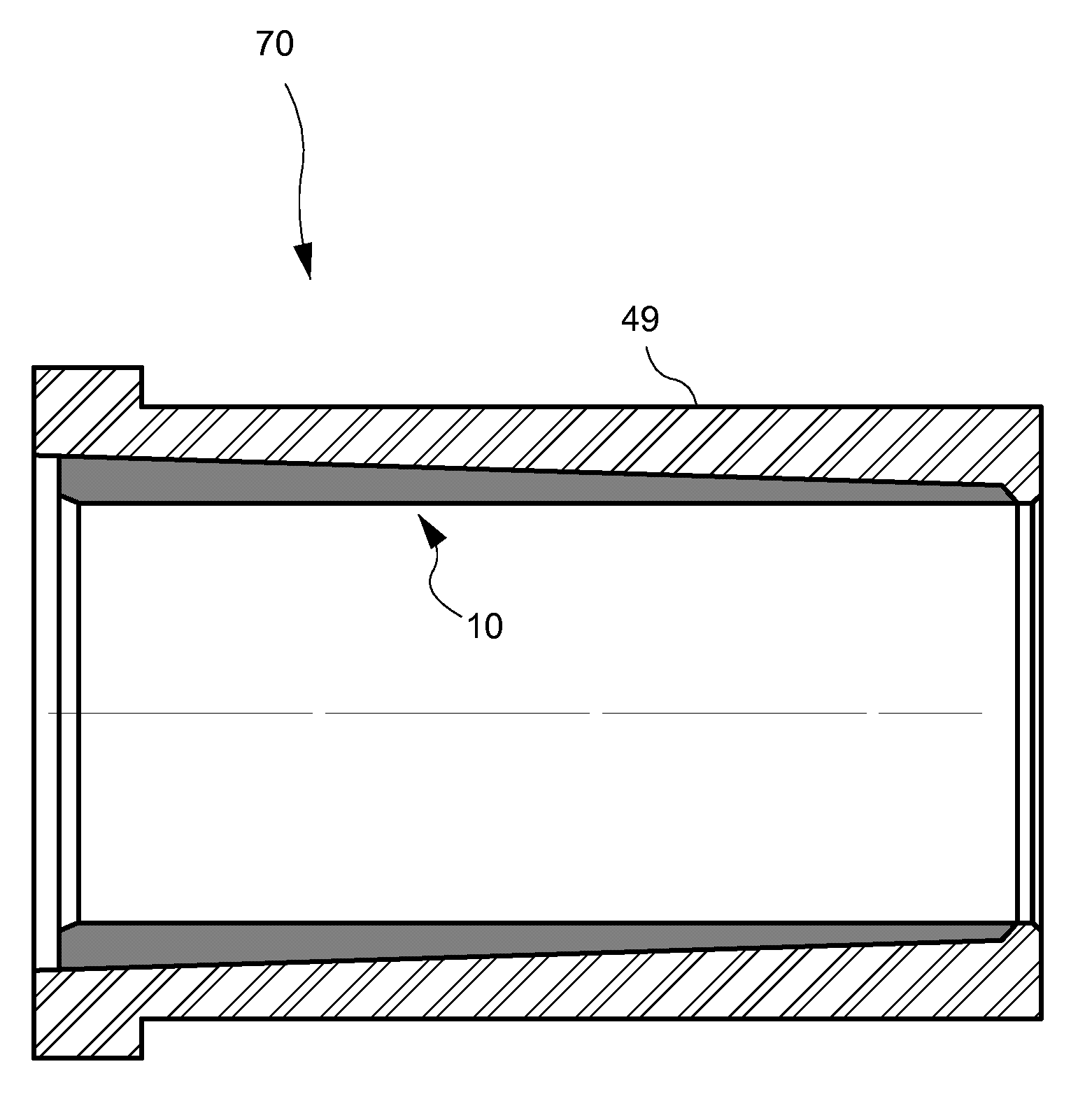
[0031]The very high modulus of elasticity of cemented carbide as described herein imparts substantial strength to certain layered bimetallic structures (e.g., mud pump liners). If a cemented carbide lining or preform sleeve is fused to the inner surface of a tubular hull, as by hot isostatic pressure (HIP) or centrifugal casting, the cemented carbide is held in compression by hull hoop stress resulting from the relatively greater radial shrinkage of the hull as it cools around the cemented carbide. The high modulus of elasticity of the cemented carbide then reduces the stress on the liner hull by as much as 50% when the liner is under pressure in service.

[0032]To ensure that the desired hull stress reduction is achieved, the carbide and the hull must be fused or welded together. A bond that is less strong, such as the shrink fit of a carbide sleeve in a hull (analogous to the shrink fit of a conventional chrome-iron sleeve within a hull), will not achieve the desired hull stress red...


PUM

PropertyMeasurementUnit
pressuresaaaaaaaaaa
pressureaaaaaaaaaa
radial distanceaaaaaaaaaa

Abstract

Differential coefficients of thermal expansion facilitate close approximation during cooling of a sintered cemented carbide tubular inlay preform (e.g., a first tubular portion) which is vacuum brazed within a corresponding tubular metal hull (e.g., a second tubular portion). Such a tubular inlay preform comprises at least one metal carbide and at least one nonvolatile cement which have previously been compressed and sintered in a predetermined shape. The tubular inlay preform's modulus of elasticity and thermal conductivity substantially exceed the corresponding parameters of the tubular metal hull, whereas the hull's coefficient of thermal expansion exceeds that of the preform. Longitudinal movement of a tubular inlay preform within a tubular hull may be limited by structural features of the hull and / or preform. Additionally, circumferential compression of a tubular inlay preform due to hoop stress in a corresponding tubular metal hull increases as the hull cools after vacuum brazing.

Description

[0001]This application is a continuation-in-part of U.S. Ser. No. 12 / 429,199 filed 24 Apr. 2009, which was a continuation-in-part of U.S. Ser. No. 11 / 382,298 filed 9 May 2006 (now U.S. Pat. No. 7,540,470).FIELD OF THE INVENTION[0002]The invention relates generally to high-pressure pumps used, for example, in oil and gas field operations. Components of such pumps incorporate structural features and / or fabrication techniques relating generally to inlays comprising one or more metal carbides on metal substrates.BACKGROUND[0003]Engineers typically design high-pressure oil field pumps in two sections; the (proximal) power section (herein “power end”) and the (distal) fluid section (herein “fluid end”). The power end usually comprises a crankshaft, reduction gears, bearings, connecting rods, crossheads, crosshead extension rods, etc. In mud pumps, the power end also contains a liner within which a piston is moved in a reciprocating manner by a piston rod. Notwithstanding their location re...

Claims


Application Information

Patent Timeline
Patent Type & Authority Patents(United States)
IPC IPC(8): F16K51/00
CPCF04B53/102F04B53/1082F04B53/1087F16K1/465F16K31/041B22F5/106B22F7/08B22F2998/10B22F2999/00C22C29/06C22C29/08Y10T137/7036C22C1/051B22F3/04B22F3/10B22F3/15B22F2207/20B22F7/064
Inventor BLUME, GEORGE H.
Owner NOVATECH HLDG CORP
Why Eureka
Try Eureka