Voltage regulated DC supply circuit for a wire feed drive system

a wire feed drive and voltage regulation technology, applied in the direction of electric controllers, dynamo-electric converter control, instruments, etc., can solve the problem that the wire feed drive system no longer continuously outputs the desired amount of wires, the length of cables increases, and the torque requirement of the motor is impacted

Active Publication Date: 2012-09-11
ILLINOIS TOOL WORKS INC
View PDF13 Cites 13 Cited by
  • Summary
  • Abstract
  • Description
  • Claims
  • Application Information

AI Technical Summary

Benefits of technology

[0005]The present disclosure is directed to systems and methods relating to a boosting rectifier and feeder motor drive circuit. One embodiment of the present disclosure relates to the elimination of undesirable wire feeder inconsistencies due to factors such as motor loading conditions, increased distance between the primary power source and the wire feeder, and so forth. In particular, the present disclosure provides a circuit that may be used to produce a regulated DC supply voltage from a variable input AC line voltage, chop the DC supply voltage and deliver a pulse width modulated motor voltage to a wire feed motor in the wire drive assembly. In certain embodiments, the circuit may contain power factor correction circuitry, which may reduce the size of circuit components and increase the utilization of available AC current. Exemplary controller logic that may be used to control the operation of the boosting rectifier and feeder motor drive circuit is provided.

Problems solved by technology

Additionally, factors associated with the way a user sets up the wire feed system, such as positioning the wire feeder in a location remotely located from the primary power source, applying high drive roll tension, increasing cable length, and so forth can impact the motor torque requirement.
When the magnitude of the DC supply voltage falls below the requirement to maintain desired wire feed speed, the wire feed drive system no longer continually outputs the desired amount of wire.

Method used


Image

  • Voltage regulated DC supply circuit for a wire feed drive system
  • Voltage regulated DC supply circuit for a wire feed drive system
  • Voltage regulated DC supply circuit for a wire feed drive system

Examples


Embodiment Construction

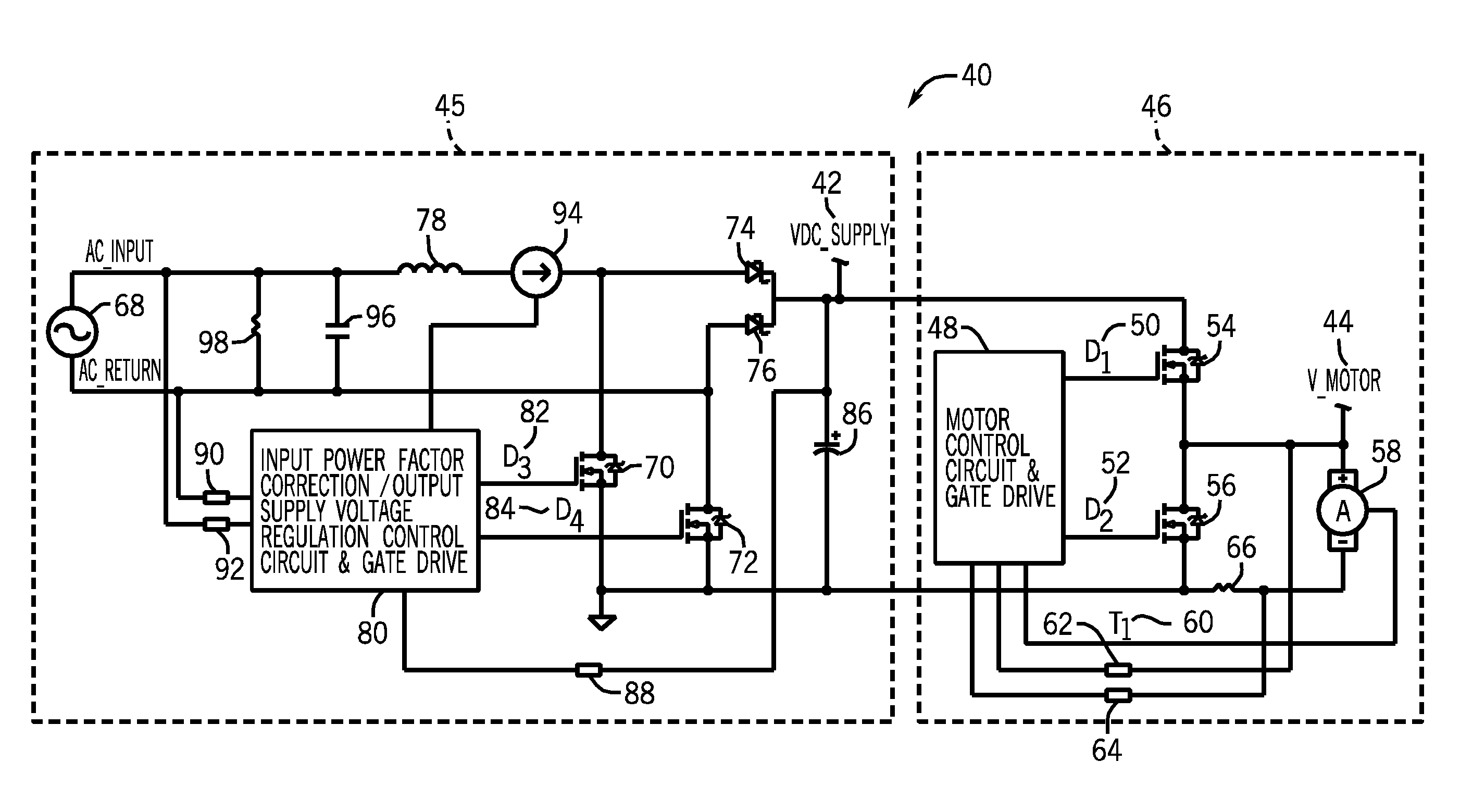
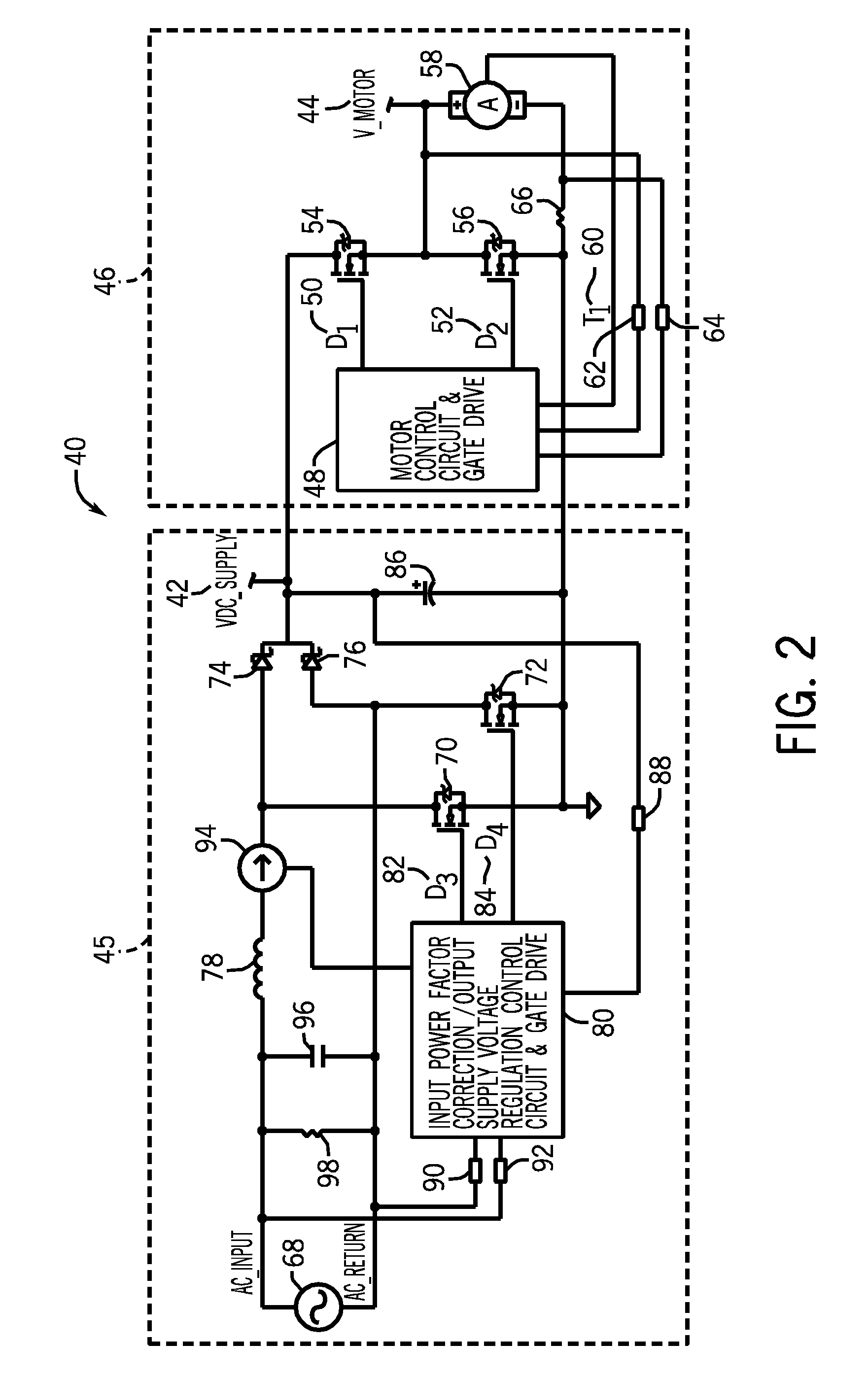
[0014]As discussed in further detail below, various embodiments of a circuit that may be used to produce a regulated DC supply voltage from a variable input AC line voltage for a wire feed motor that supplies wire to a welding operation are provided. During operation, the circuit chops the DC supply voltage and delivers a pulse width modulated motor voltage to a wire feed motor in a wire drive assembly. The circuit is capable of power factor correction, which may increase circuit efficiency as compared to traditional circuits, thereby reducing the size of circuit components. The disclosed embodiments include current paths that may be established through the circuit during the positive and negative half cycles of an AC input voltage. The circuit is capable of maintaining the constant DC supply voltage regardless of input voltage, loading restrictions, and so forth, ensuring that user setup and equipment variability do not affect wire feeder performance during a weld.

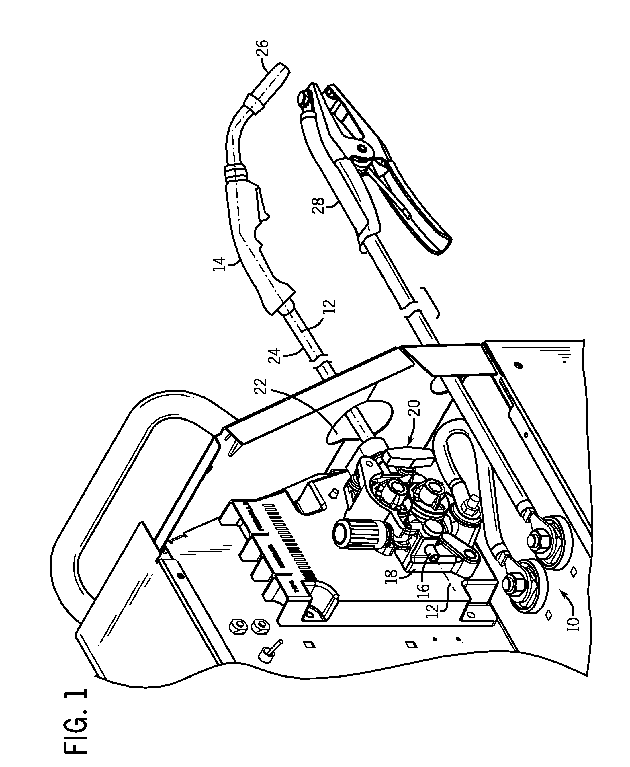
[0015]FIG. 1 illu...


PUM


Abstract

Systems and methods relating to a boosting rectifier and feeder motor drive circuit are provided. The circuit may be used to produce a regulated DC supply voltage from a variable input AC line voltage, chop the DC supply voltage and deliver a pulse width modulated motor voltage to a wire feed motor in the wire drive assembly. One embodiment relates to elimination of undesirable wire feeder inconsistencies due to motor loading conditions, distance between the primary power source and the wire feeder, and so forth. In certain embodiments, the circuit may contain power factor correction circuitry, which may reduce the size of circuit components due to increased efficiency. Current paths through the circuit during the positive and negative half cycles of the AC input voltage are provided. Exemplary controller logic that may be used to control the operation of the boosting rectifier and feeder motor drive circuit is provided.

Description

CROSS REFERENCE TO RELATED APPLICATIONS[0001]This application is a U.S. Non-provisional Patent Application of U.S. Provisional Patent Application No. 61 / 085,334, entitled “Voltage Regulated DC Supply Circuit for a Wire Feed Drive System”, filed Jul. 31, 2008, which is herein incorporated by reference.BACKGROUND[0002]The present disclosure relates generally to welding systems and welding wire feed systems, and more particularly, to systems and methods for producing a regulated DC supply voltage from a variable AC source voltage.[0003]Many types of welding systems, such as metal inert gas (MIG) welding, utilize continuously fed consumable wire from a welding torch during a welding operation. A wire feed motor is responsible for maintaining a continuous wire feed to the welding operation even when system demands require the motor torque to increase. Common factors such as wire diameter, wire type, drive roll type, drive roll tension, wire spool tension, torch cable length, and torch ca...

Claims


Application Information

Patent Timeline
Patent Type & Authority Patents(United States)
IPC IPC(8): G05B11/28
CPCH02P7/292
Inventor VEIK, BRIAN JAMES
Owner ILLINOIS TOOL WORKS INC
Why Eureka
Try Eureka