Electronic control for a hydraulically driven auxiliary power source

a technology of electric control and hydraulic system, applied in the direction of electric generator control, positive displacement liquid engine, fluid coupling, etc., can solve the problems of engine electrical power, engine speed variations wreak havoc, and difficulty in maintaining precise frequency output for controlling

Active Publication Date: 2012-09-18
UUSI
View PDF18 Cites 42 Cited by
  • Summary
  • Abstract
  • Description
  • Claims
  • Application Information

AI Technical Summary

Benefits of technology

[0010]Accordingly, it is an aspect of the present invention to provide a hydraulic control system for generating precise electrical output characteristics, particularly frequency and voltage output, along with prolonging the life of the system, thus reducing warranty returns and costs associated therewith.
[0016]Furthermore, the system controller may include an overtemperature shutdown sub-circuit for generating a control signal controlling the valve assembly when fluid temperature becomes too hot for safe operation such that fluid bypasses the motor, thereby shutting down the auxiliary power source. Additionally, the control circuit can be equipped with an emergency override accessible by an operator for instructing the system controller to continue system operation even though unsafe operating conditions exist that may damage the system.
[0019]In an alternative embodiment of the present invention, the valve assembly can be eliminated. Rather then bypassing the pump output about the motor, a variable displacement of the pump is utilized having a pump displacement input. The effect of displacement of the pump can be varied in order to achieve a desired hydraulic motor input flow or pressure automatically increasing pump displacement when the flow or pressure drops and then decreasing pump displacement when the hydraulic motor input flow or pressure exceeds a specified level.
[0025]Further, the method of operating the hydraulic control system may include preventing over-temperature damage to the system when the sensed fluid temperature exceeds safe operating temperature. Preventing over-temperature damage may involve annunciating the existence of over-temperature conditions to an operator when a first high temperature is obtained, triggering a timer to begin counting down a specified time when a second high temperature is obtained, and bypassing all fluid flow to the motor when the timer has expired. Bypassing all fluid flow to the motor can involve opening an electronically controlled hydraulic valve disposed within the fluid circuit such that fluid is directed entirely to a bypass conduit. Additionally, the method may include overriding the bypassing step upon receipt of an emergency override instruction from an operator to prevent shutdown and keep the system operating.

Problems solved by technology

However, numerous modules and devices for the vehicle as well as the engine require electrical power.
While this will indeed operate a generator, variations in engine speed will wreak havoc with characteristics of power output and therefore with equipment which is dependent upon stable voltage and frequency characteristics of electrical power.
However, such systems can have difficulty maintaining precise frequency output for controlling the most sensitive AC equipment and are often susceptible to premature mechanical failure.

Method used


Image

  • Electronic control for a hydraulically driven auxiliary power source
  • Electronic control for a hydraulically driven auxiliary power source
  • Electronic control for a hydraulically driven auxiliary power source

Examples


third embodiment

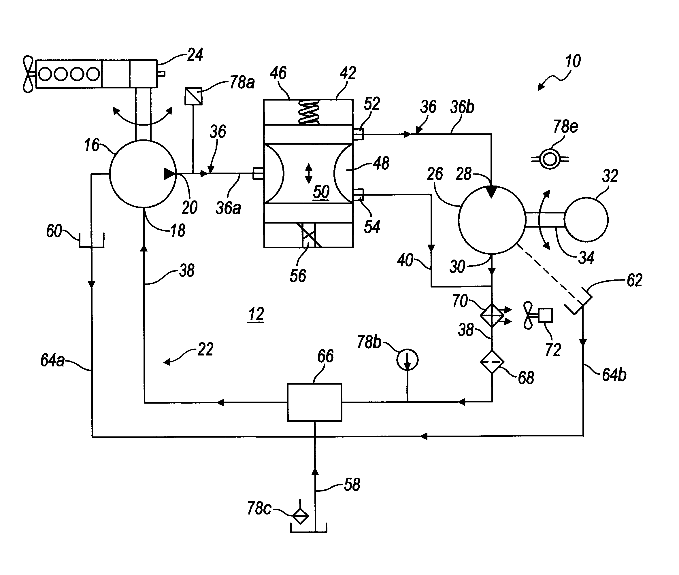
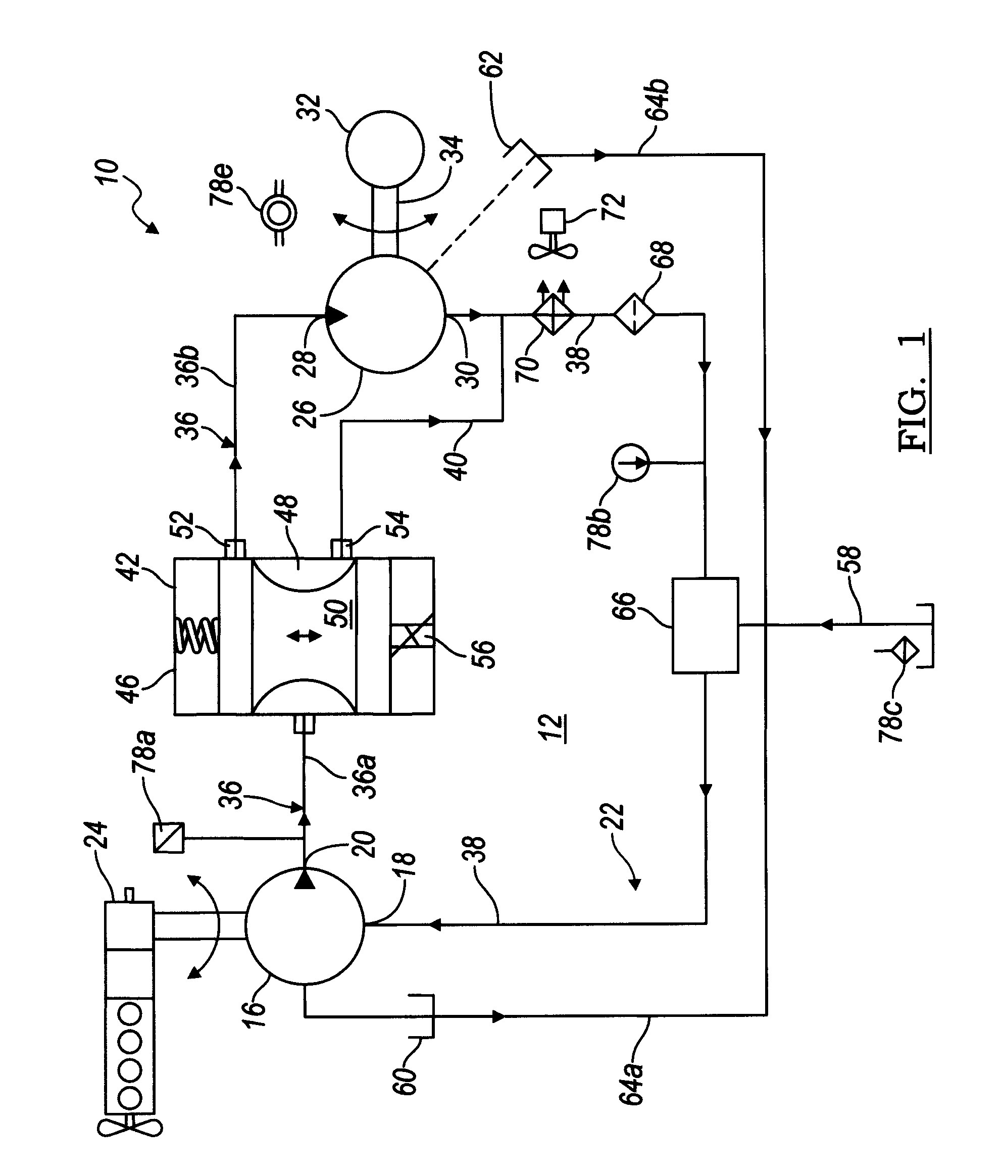
[0078]the present invention is illustrated in FIG. 5. A hydraulically driven generator system 110 is similar to system 10 described with reference to FIG. 1, however rather than using a control valve assembly 42 to regulate the amount of the output of pump 16 that passes through motor 26, a variable displacement pump 112 is utilized which has an external input which enables the control system to vary the pump displacement to achieve the desired flow rate needed for motor 36. Hydraulic control circuit 114 of the FIG. 5 embodiment is otherwise generally similar to control circuit 12 utilized in the FIG. 1 embodiment and like components function in a similar manner as described previously.

[0079]In operation the output from pump 112 provides hydraulic fluid to motor 26. As previously described, control valve 42 is utilized in the FIG. 1 embodiment is no longer required provided the pump minimum displacement is sufficiently low. If the minimum pump displacement is substantial, i.e., over...

seventh embodiment

[0090]Referring now to FIG. 12, with continual reference to FIG. 1, the present invention is illustrated. A hydraulically driven generator system 10 shown in FIG. 12 is the same as system 10 described with reference to FIG. 1 with the exception that one or more additional control valve assemblies 131, 132 are employed. For instance, system 10 may include a control valve assembly 132 disposed serially and / or parallel with respect to supply conduit 36 such that it is interposed between outlet 20 of pump 16 and control valve assembly 42. Control valve assembly 132 may be employed to warm and / or isolate and protect the rest of system 10 from conditions existing at pump 16 such as cold hydraulic fluid. Control valve assembly 132 may be slowly opened to allow fluid to propagate to the rest of system 10 as conditions improve such as the hydraulic fluid warming to an appropriate temperature.


PUM


Abstract

A hydraulic system includes a variable displacement hydraulic pump connectable to a power source, a hydraulic motor, a fluid circuit, a pump displacement control, and a controller. The pump has an inlet for receiving fluid, an outlet for discharging pressurized fluid, and a pump displacement input. The motor has an inlet for receiving pressurized fluid and an outlet for discharging spent fluid. The fluid circuit includes a supply conduit for conducting fluid discharged by the pump to the motor and a return conduit for returning fluid discharged by the motor to the pump. The pump displacement control cooperates with the pump displacement input to vary pump displacement. The controller communicates with the pump displacement control to control the pump output such that the motor is driven at a constant speed to thereby drive a generator connected to the motor at a constant speed despite speed fluctuations of the power source.

Description

CROSS-REFERENCE TO RELATED APPLICATIONS[0001]This application is a continuation-in-part of U.S. application Ser. No. 12 / 324,025, filed Nov. 26, 2008; which is a continuation-in-part of U.S. application Ser. No. 11 / 275,574, filed Jan. 17, 2006, now U.S. Pat. No. 7,459,800.[0002]This application is related to U.S. application Ser. No. 11 / 037,984, filed Jan. 18, 2005, now U.S. Pat. No. 7,053,498.BACKGROUND OF THE INVENTION[0003]1. Field of the Invention[0004]The present invention is directed to an electronic control for hydraulic systems, and more particularly to precision control of hydraulically driven generators for stabilizing frequency and voltage output characteristics.[0005]2. Background Art[0006]Most engine driven vehicles utilize an internal combustion engine as the primary power source for propelling a vehicle. However, numerous modules and devices for the vehicle as well as the engine require electrical power. Typically, a rechargeable battery is provided with the vehicle as...

Claims


Application Information

Patent Timeline
Patent Type & Authority Patents(United States)
IPC IPC(8): F03B13/00F03B13/10H02P9/04
CPCF15B7/008F16H61/4035F16H61/4043F16H61/4061F16H61/431F16H61/461F16H61/47H02P9/009H02P9/48F15B21/08H02P2101/45F15B2211/20523F15B2211/20538F15B2211/40515F15B2211/413F15B2211/427F15B2211/45F15B2211/6333F15B2211/6336F15B2211/6343F15B2211/6656F15B2211/7058H02P2101/30
Inventor BOISVERT, MARIO P.KIENITZ, THOMASWASHELESKI, JOHN M.BLANK, ANDREW
Owner UUSI
Why Eureka
Try Eureka