Apparatus for manufacturing vitreous silica crucible

Active Publication Date: 2012-10-09
SUMCO CORP
View PDF23 Cites 3 Cited by
  • Summary
  • Abstract
  • Description
  • Claims
  • Application Information

AI Technical Summary

Benefits of technology

[0037]According to a method of manufacturing a vitreous silica crucible of the present invention, fusion and vitrification can be performed on silica powder while suppressing a gas exchange between the lower section in which the mold is disposed, and the upper section in which the electrode controlling unit is disposed. When a vitreous silica crucible is manufactured by using the method, the electrode driving unit inside the upper section can be suppressed from being contaminated by the silica fume generated while fusing the silica powder, and thus the wear particles can be prevented from being generated according to wear due to minute silica particles intruding into the sliding portion. Also, the metal fragments or wear particles generated in the upper section can be prevented from intruding into the lower section. Accordingly, accordin

Problems solved by technology

However, silica fume cannot be suppressed from floating inside an apparatus for manufacturing a vitreous silica crucible, in the technology of controlling the characteristics of a material of the carbon electrode, as described in JP-A-2007-273206.
Intrusion of fume, which is generated during an operation according to manufacturing of the vitreous silica crucible, into a gap of control members in these apparatuses is a reason for damage due to wear.
Accordingly, an operation of removing the fume, exchanging worn out parts, or the like is required during maintenance, and thus efficiency of the operation of manufact

Method used


Image

  • Apparatus for manufacturing vitreous silica crucible
  • Apparatus for manufacturing vitreous silica crucible
  • Apparatus for manufacturing vitreous silica crucible

Examples


first embodiment

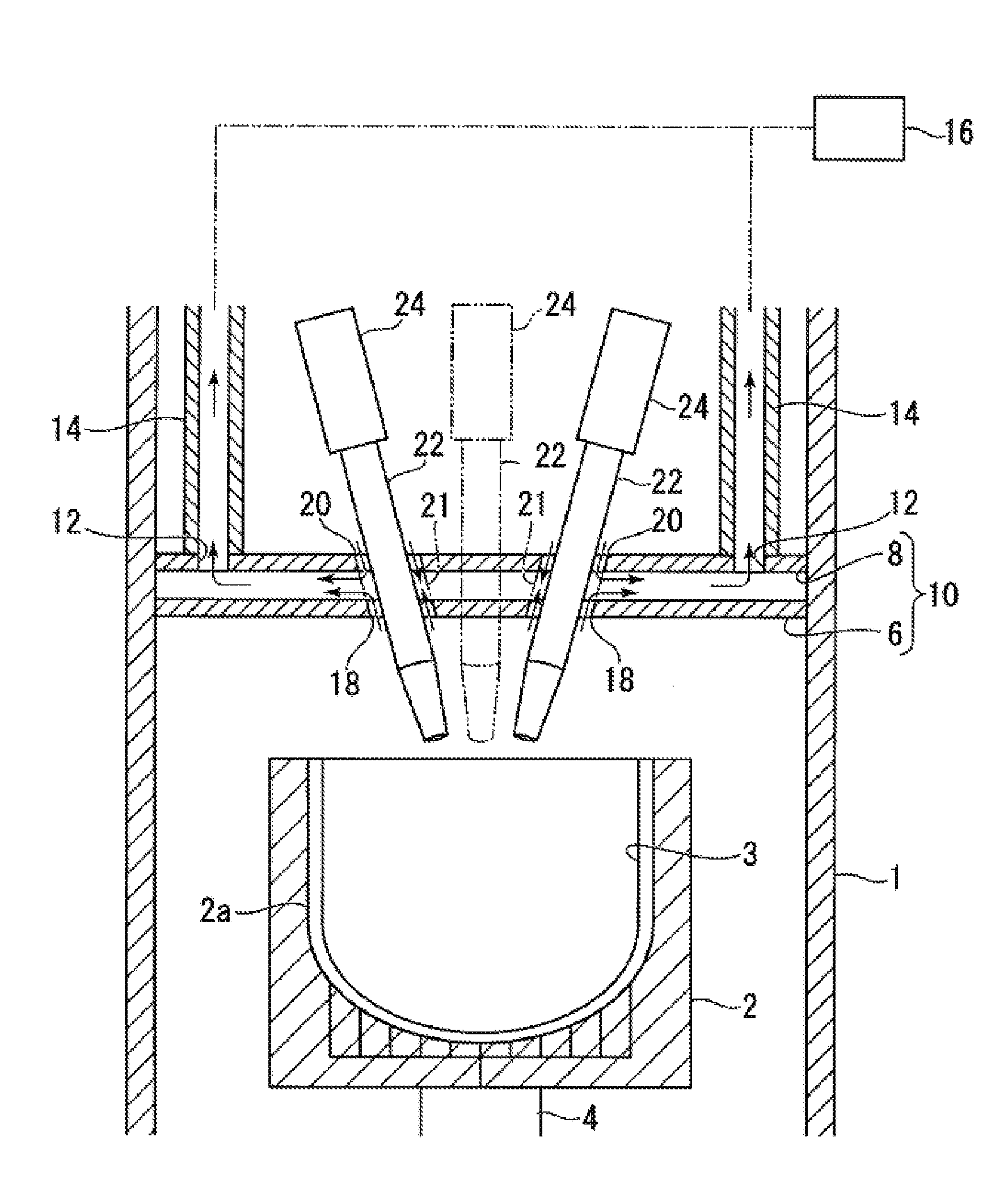
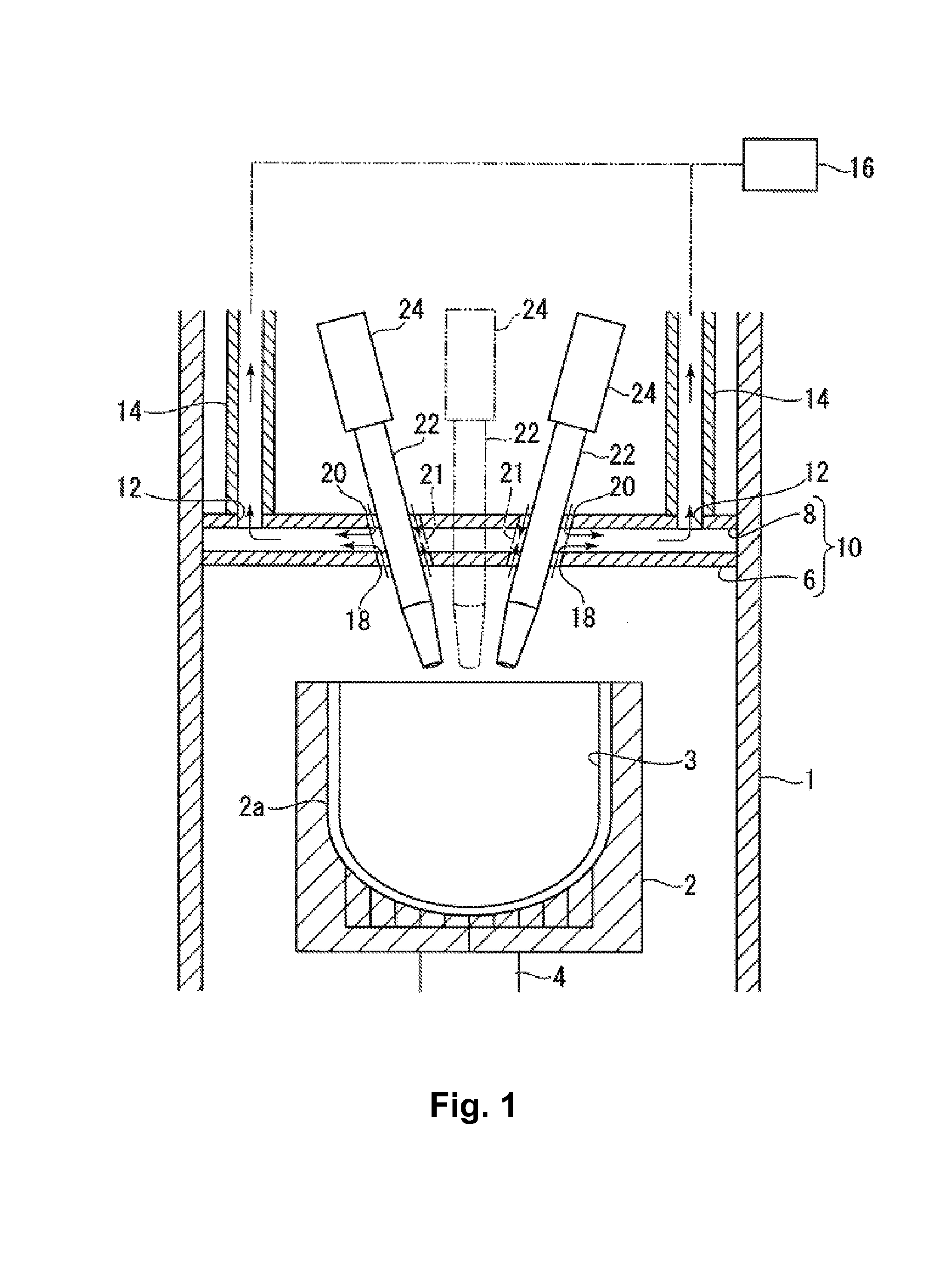
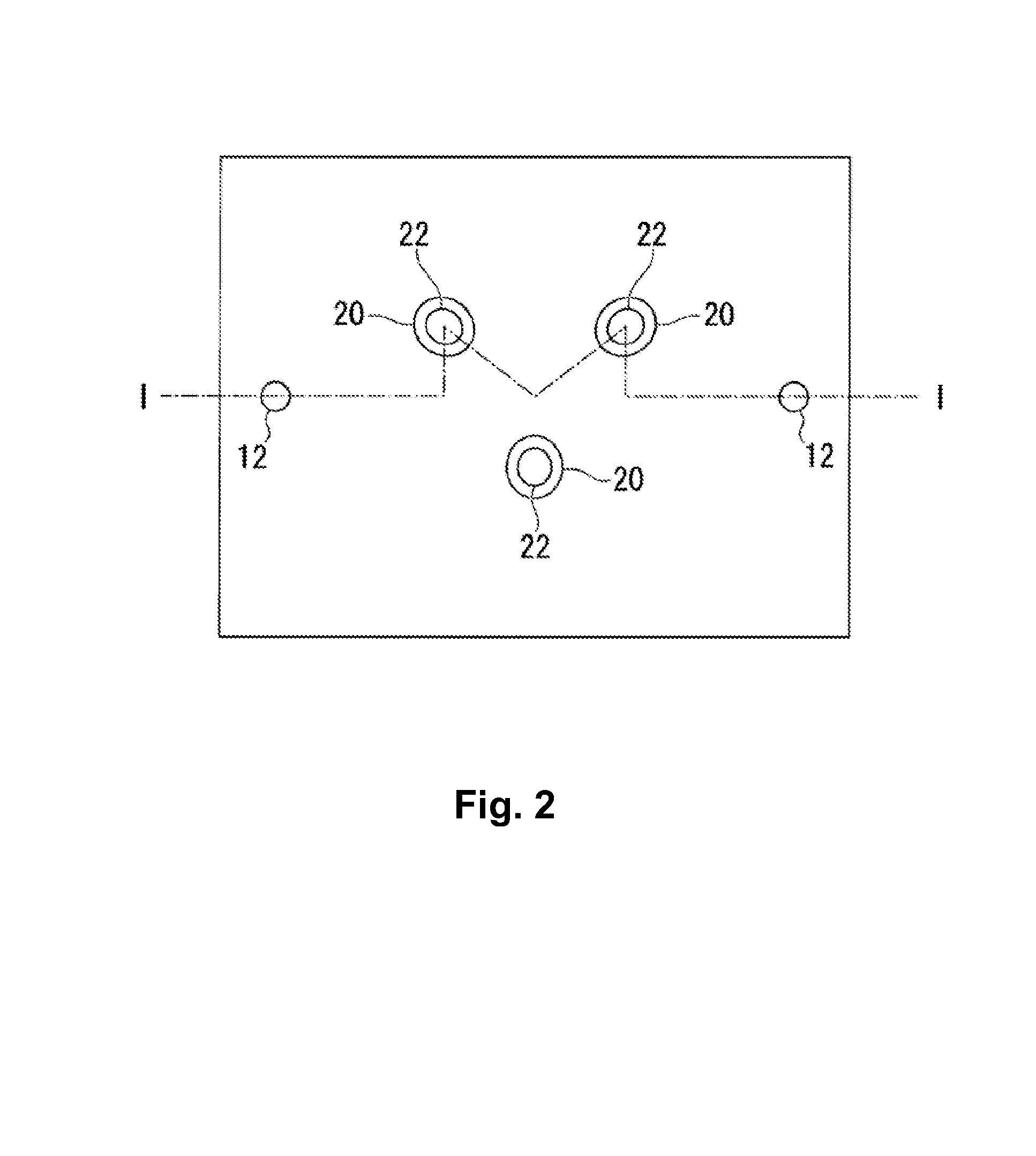
[0045]FIG. 1 is a schematic front cross-sectional view for explaining an apparatus for manufacturing a vitreous silica crucible, according to a first embodiment of the present invention, taken along a line I-I of FIG. 2, and FIG. 2 is a horizontal cross-sectional view of the same apparatus for manufacturing a vitreous silica crucible.

[0046]The apparatus includes an apparatus chamber surrounded by a side wall 1 capable of blocking the inside of the apparatus where arc flames are generated from the outside of the apparatus. The side wall 1 may be formed of a metal or a structural material such as concrete or the like, as long as blocking (or reduction and alleviation outside of the apparatus) of an atmosphere gas, temperature, noise, vibration, etc. required in manufacturing a vitreous silica crucible is possible in the inside and outside of the apparatus. Alternatively, a heat resistant material, such as heat resistant ceramics, or the like, may be used for at least a part of the sid...

second embodiment

[0070]FIG. 3 is a view for explaining another embodiment of the present invention. The same reference numerals of FIG. 1 are used for elements having the same structure as the first embodiment, and descriptions thereof will not be repeated.

[0071]In the present embodiment, a plurality of air supply holes 13 are formed on the second barrier wall, and the intermediate section communicates with an air supply device 17 through an air supply path 15 having a pipe shape and extending upward from the air supply hole. Clean air is supplied from the air supply device 17 through a HEPA filter (high efficiency particulate air filter).

[0072]A method of manufacturing a vitreous silica crucible, according to the present embodiment will be described.

[0073]First, silica powder is deposited on the inner surface of the mold 2, and the silica powder molded body 3 is formed approximately corresponds to a shape of a target vitreous silica crucible.

[0074]Next, the electrode tip is disposed at a predetermi...

example 1

[0093]One hundred vitreous silica crucibles having an outer diameter of 802 mm were manufactured by using the apparatus having the structure of the first embodiment. After the manufacturing, a yield was determined by visually inspecting products to determine whether impurities were adhered to the bottom surface and whether the bottom surface was uneven.


PUM

PropertyMeasurementUnit
Flow rateaaaaaaaaaa

Abstract

During fabrication of a vitreous silica crucible, contamination of the vitreous silica crucible due to wear particles and debris of components of an apparatus for manufacturing a vitreous silica crucible is reduced by preventing damage and wear of the components of the apparatus due to silica fume. The apparatus for manufacturing a vitreous silica crucible is divided into a lower section for accommodating a mold and a mold driving system and an upper section for accommodating an arc electrode driving system, wherein a sectioning member including one or more communication paths for allowing penetration of arc electrodes, thereby the air flow is controlled so as to reduce exchange between gas in the upper section and gas in the lower section.

Description

BACKGROUND OF THE INVENTION[0001]1. Field of the Invention[0002]The present invention relates to an apparatus and method for manufacturing a vitreous silica crucible, which is capable of improving a yield of a crucible by reducing contamination generated during fabrication of a vitreous silica crucible, while enabling stable operation for a long time by protecting a main body of an apparatus.[0003]2. Description of Related Art[0004]Currently, growing of silicon single crystal constituting a raw material of a semiconductor wafer is mainly performed by using a Czochralski (CZ) method. In the Czochralski method, a seed crystal is dipped in a silicon melt accommodated in a crucible, and the seed crystal is pulled up while being rotated, thereby growing a single crystal from below the seed crystal.[0005]In the growing of the silicon single crystal, a vitreous silica crucible is generally used so as to avoid impurities being mixed with the silicon melt. Specifically, in order to grow a hi...

Claims


Application Information

Patent Timeline
IPC IPC(8): C03B19/09
CPCC03B19/095Y02P40/57
Inventor SUDO, TOSHIAKIFUJITA, TAKESHI
Owner SUMCO CORP
Why Eureka
Try Eureka