Solar hybrid combined cycle gas and steam power plant

a combined cycle and power plant technology, applied in the direction of machines/engines, mechanical equipment, transportation and packaging, etc., can solve the problems of unsuitable for larger units, limited upper process temperatures, disadvantages for efficiency and cost, etc., and achieve the effect of facilitating an advantageous installation of power plant components

Active Publication Date: 2012-10-16
DRESDEN UNIVERSITY OF TECHNOLOGY
View PDF18 Cites 14 Cited by
  • Summary
  • Abstract
  • Description
  • Claims
  • Application Information

AI Technical Summary

Benefits of technology

[0016]Thus, it is an object of the present invention to provide a unit and a method which facilitate heat transfer and coupling of solar heat into a process of a natural gas and steam power plant, wherein in the locations for absorbing solar heat and coupling the heat into the process are spatially separated from one another. In order to reduce the consumption of fossil fuels, a high percentage of the heat required for the process shall be provided from solar energy.

Problems solved by technology

The limited upper process temperatures, however, on the other hand side are disadvantageous for efficiency and cost.
The gas turbine is arranged in the tower proximal to the receivers and thus unsuitable for larger units.
Thus, high process temperatures and thus high percentages of solar heat induction combined with different primary energies can only be facilitated on a limited basis.
On the other hand side low process temperatures cause low efficiency.
For these reasons so far a disadvantageous compromise is made between high process temperature, solar portion of heat induction and supply safety or supply quality with respect to electric energy.
Furthermore the use of gas turbine units with solar heat coupled into the process is limited to small units as long as the gas turbine has to be positioned proximal to the receiver.

Method used


Image

  • Solar hybrid combined cycle gas and steam power plant
  • Solar hybrid combined cycle gas and steam power plant
  • Solar hybrid combined cycle gas and steam power plant

Examples


Embodiment Construction

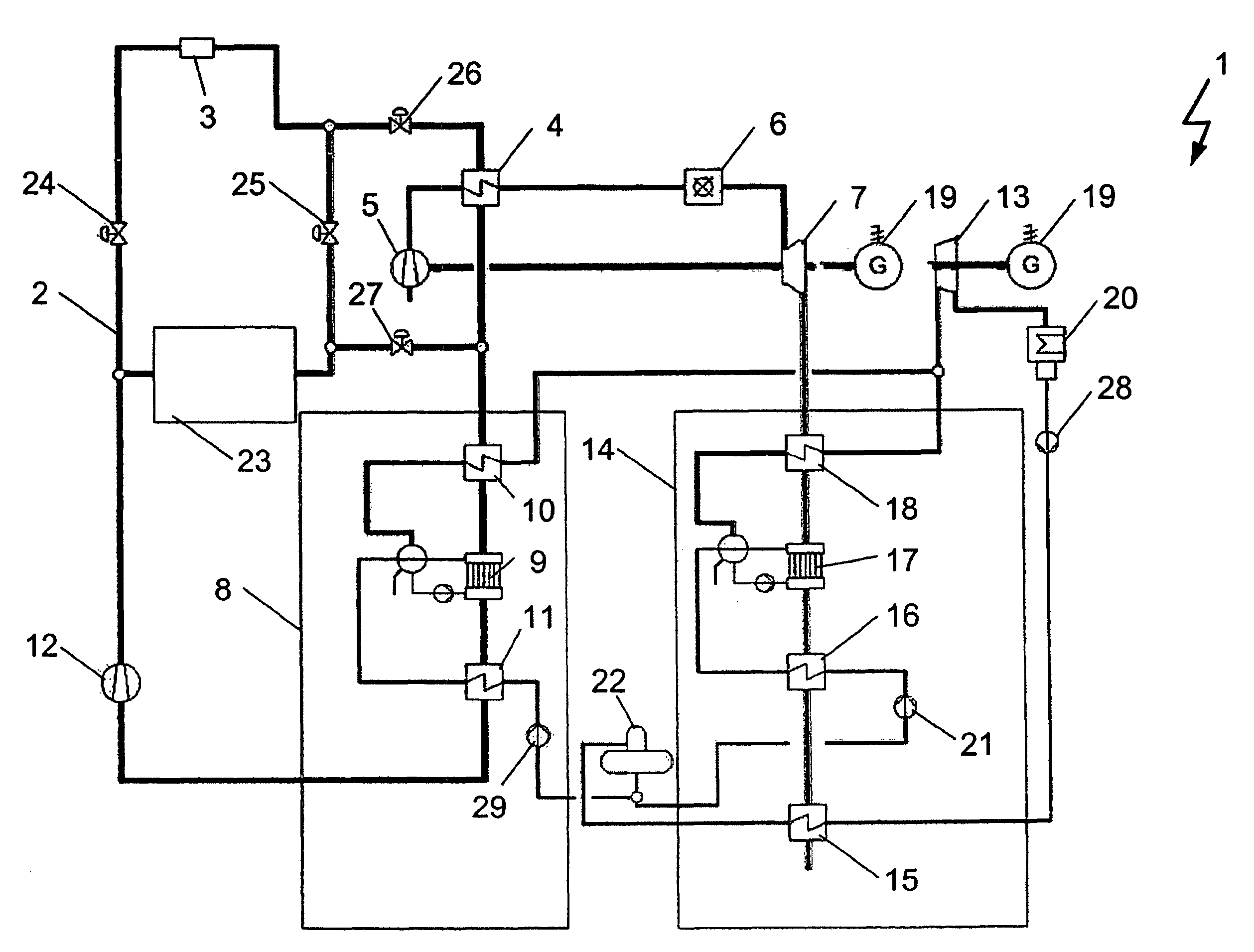
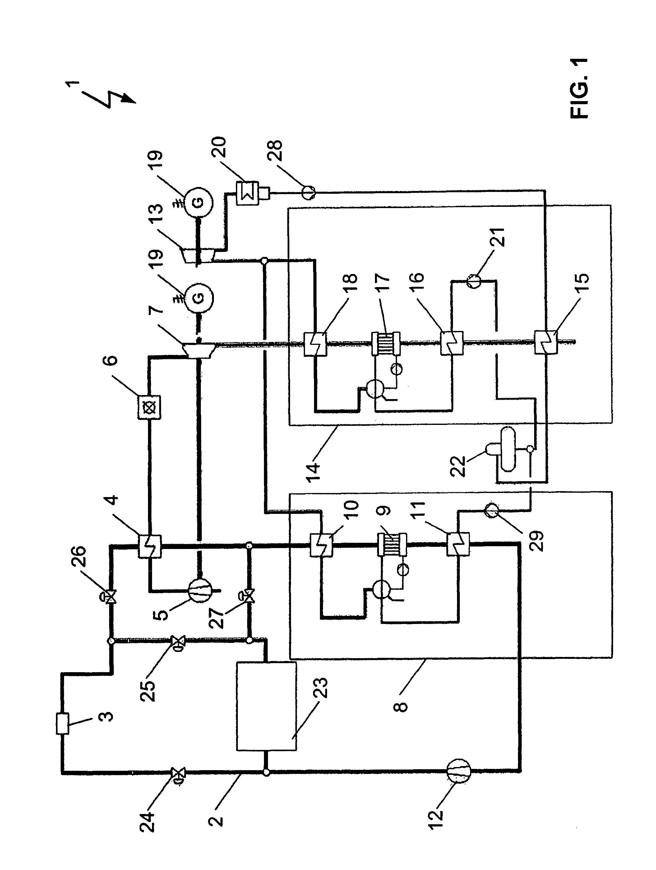
[0062]FIG. 1 illustrates the simplified schematic of a solar hybrid combined cycle gas and steam power plant 1 with a primary solar heat transfer medium cycle 2 with one respective economizer 11, 16 in the solar boiler 8 and in the waste heat boiler 14 in which the feed water for a steam turbine unit is preheated. The power plant essentially includes a gas turbine unit with a compressor 5, a combustion chamber 6 and a gas turbine 7 with a waste heat boiler 14 arranged downstream which also represents a component of the steam turbine unit. The hot exhaust gas of the gas turbine 7 is used in the waste heat boiler 14 for generating superheated steam. Parallel thereto the steam can also be provided in the solar boiler 8. Additional heat is supplied in a super heater 10, 18 to water that is evaporated at saturation temperature in an evaporator 9, 17. Additional heating of the steam increases the temperature and the specific volume of the steam so that it is superheated. From the solar bo...


PUM


Abstract

A solar hybrid combined cycle gas-steam power plant and method including a solar unit, a gas turbine unit and a steam turbine unit. The solar unit includes a receiver. The gas turbine unit includes a gas turbine with a waste heat boiler arranged downstream, and a steam turbine with a feed water heater. The power plant includes a heat transfer medium cycle for transferring solar heat. The heat transfer medium cycle is coupled to the gas turbine unit through a gas turbine heat exchanger and to the steam turbine unit through a solar boiler. Alternatively to the gas turbine unit and the steam turbine unit, the solar hybrid combined cycle power plant includes an integrated gas-steam turbine having a waste heat boiler arranged downstream, wherein the heat transfer medium cycle is coupled to the integrated gas-steam turbine through the gas turbine heat exchanger and through the solar boiler.

Description

RELATED APPLICATIONS[0001]This patent application is a continuation of International patent application PCT / EP2009 / 062898, filed on Oct. 5, 2009 claiming priority from and incorporating by reference German patent application DE 10 2008 051 384.9, filed on Oct. 11, 2008, both of which are incorporated herein by this reference.FIELD OF THE INVENTION[0002]The invention relates to a solar hybrid combined cycle gas and stream power plant including a solar unit, a gas turbine unit with a waste heat boiler and a steam turbine unit and a heat transfer medium cycle for utilizing solar heat. The invention further relates to a method for operating a solar hybrid combined cycle gas steam power plant with a gas turbine process and a steam turbine process, wherein solar heat is coupled into the processes through a heat transfer medium cycle.BACKGROUND OF THE INVENTION[0003]Environmental problems increasing worldwide, increasing energy demand and resource shortages require new technologies for pow...

Claims


Application Information

Patent Timeline
Patent Type & Authority Patents(United States)
IPC IPC(8): B60K16/00B60L8/00F03G6/00
CPCF01K23/10F02C1/05F03G6/064F03G6/067Y02E10/46Y02E20/16Y02T10/7072
Inventor HEIDE, STEPHANGAMPE, UWEFREIMARK, MANFRED
Owner DRESDEN UNIVERSITY OF TECHNOLOGY
Why Eureka
Try Eureka