Optical receiver for the WDM system and the method for controlling the same

a technology of optical receiver and receiver, applied in the direction of multiplex communication, electrical apparatus, wavelength-division multiplex system, etc., can solve the problems of large size and complicated optical receiver

Active Publication Date: 2012-10-16
SUMITOMO ELECTRIC IND LTD
View PDF27 Cites 4 Cited by
  • Summary
  • Abstract
  • Description
  • Claims
  • Application Information

AI Technical Summary

Benefits of technology

[0010]According to the method of the present invention, because the optical receiver monitors the electrical signals output from the respective optical receiver modules and reflects the monitored results in the bias current provided to the SOA and the temperature of the SOA, not only the control of the optical gain of the SOA which is equivalent to the optical input level to respective optical receiver modules may become stable but the optical receiver may have a compact arrangement.

Problems solved by technology

In such conventional optical receivers, the optical receiver monitors the optical input level at the upstream side of the SOA, and the bias current supplied to the SOA is so adjusted based on the monitored result, which is inevitable to provide additional optical components such as, for instance, an optical splitter and an optical attenuator, which makes the optical receiver complicated and large-size.

Method used


Image

  • Optical receiver for the WDM system and the method for controlling the same
  • Optical receiver for the WDM system and the method for controlling the same
  • Optical receiver for the WDM system and the method for controlling the same

Examples


Embodiment Construction

[0025]Next, preferred embodiments according to the present invention will be described in detail as referring to accompanying drawings. In the description of the drawings, the same numerals and symbols will refer to the same elements without overlapping explanations.

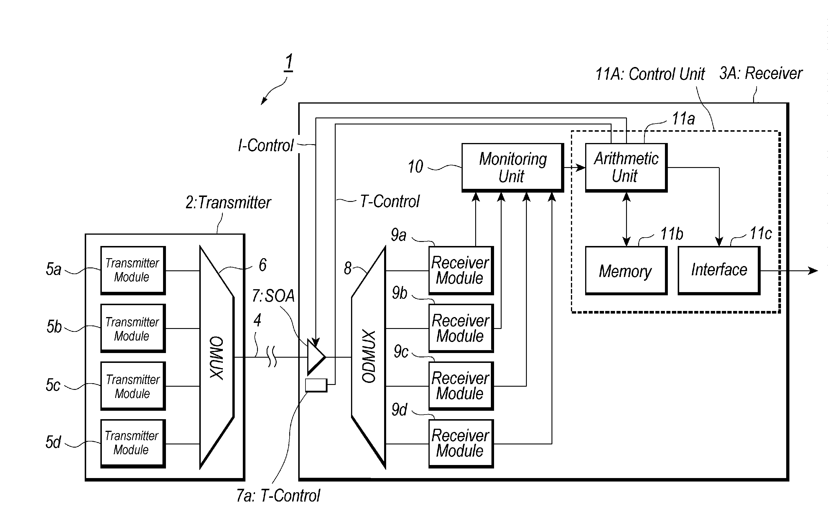
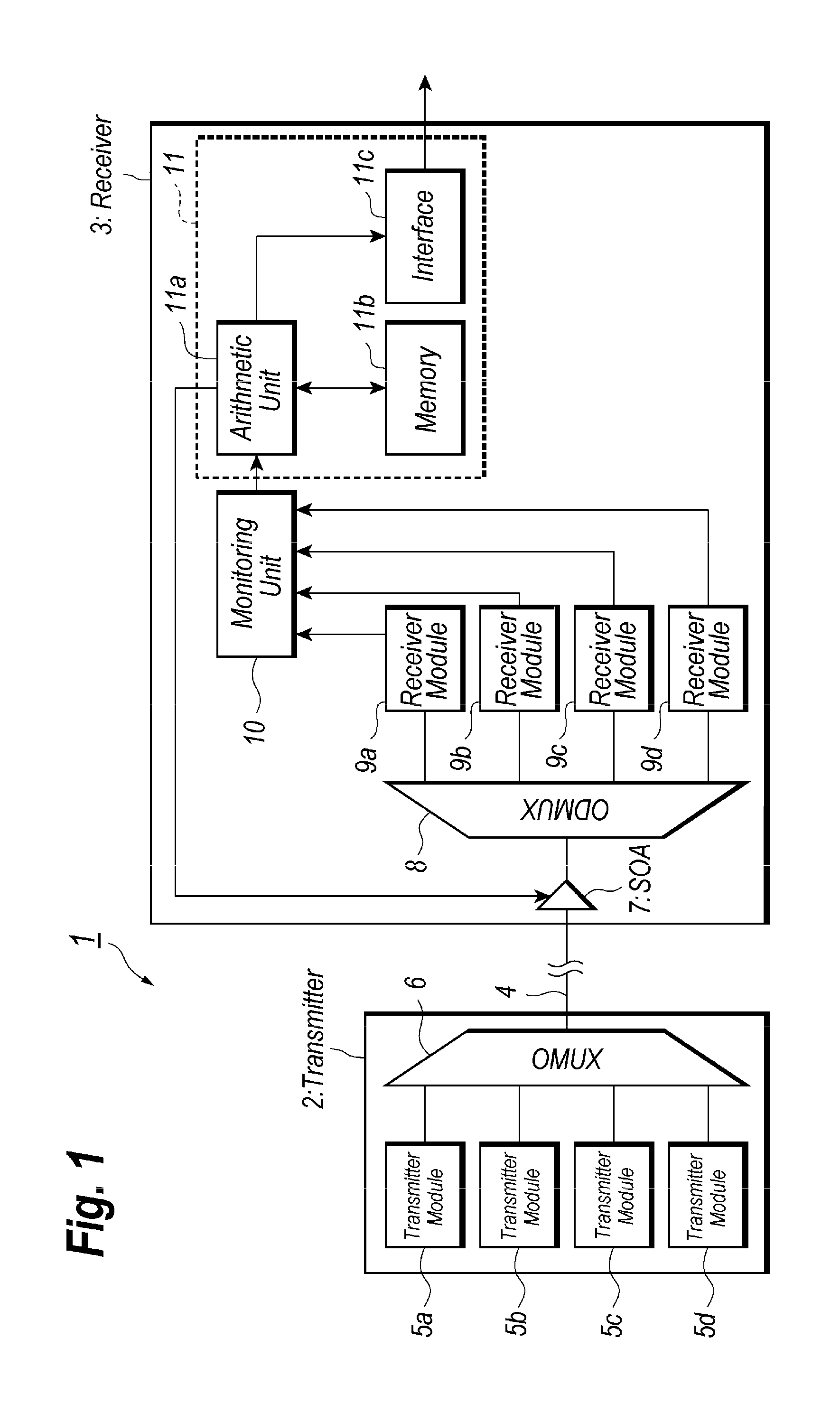
[0026]FIG. 1 illustrates a block diagram of an optical communication system according to an embodiment of the present invention, which installs an optical receiver with a function of the four wavelengths multiplexing. The optical communication system 1 shown in FIG. 1 comprises the optical transmitter 2 with the function of the four wavelengths multiplexing, the optical receiver 3 with the function of the four wavelengths de-multiplexing, and an optical medium 4 made of a single mode fiber (SMF) provided between the optical transmitter 2 and the optical receiver 3.

[0027]The optical transmitter 2 outputs multiplexed signal light to the optical medium 4. The multiplexed signal light includes four distinct optical signals e...


PUM


Abstract

An optical receiver with a simplified arrangement able to compensate the optical loss of the transmission medium is disclosed. The optical receiver of the invention includes an SOA in the front end thereof, an optical de-multiplexer, and a plurality of receiver modules that receives de-multiplexed light. The optical gain of the SOA is adjusted based on the electrical signals output from respective optical modules. When the receiver modules show the output thereof in a preset range, the bias current is kept unchanged, while, one receiver module shows the output out of the range, the bias current is incremented or decremented. When one receiver module shows the output out of the absolute maximum / minimum, the bias current is forced to the initial value.

Description

CROSS REFERENCE TO RELATED APPLICATION[0001]This patent application is a continuous-in-part of pending prior U.S. patent application Ser. No. 12 / 631,329, filed Dec. 4, 2009 by Kengo Matsumoto, titled by “OPTICAL RECEIVER FOR THE WDM SYSTEM AND METHOD TO CONTROL THE SAME”, which is hereby incorporated herein by reference in its entirety.BACKGROUND OF THE INVENTION[0002]1. Field of the Invention[0003]The present invention relates to an optical receiver applied to the wavelength division multiplexing (WDM) system and a method to control the optical receiver.[0004]2. Related Prior Art[0005]Recent optical communication system sometimes requests the transmission speed thereof reaching 100 Gbps to solve the bottleneck of the transmission capacity between the servers. One solution for the request has been proposed, in which the system includes an optical transmitter transmits signal light containing four optical signals each emitted from, for instance, an electro-absorption modulated laser ...

Claims


Application Information

Patent Timeline
Patent Type & Authority Patents(United States)
IPC IPC(8): H04B10/06
CPCH04B10/07955H04B10/674H04B10/6931H04J14/0221
Inventor OOMORI, HIROTAKA
Owner SUMITOMO ELECTRIC IND LTD
Why Eureka
Try Eureka