Process for producing ink jet head

a jet head and ink technology, applied in the field of ink jet head production, can solve the problems of low solvent resistance of alkali-developing positive resists, low sensitivity, and large energy consumption, and achieve excellent sensitivity and resolution

Inactive Publication Date: 2012-11-06
CANON KK
View PDF17 Cites 2 Cited by
  • Summary
  • Abstract
  • Description
  • Claims
  • Application Information

AI Technical Summary

Benefits of technology

[0008]It is an object of the present invention to solve the above problems and provide a process for producing an ink jet head by applying a positive resist excellent in sensitivity and resolution to the production of the ink jet head, by which deformation of an ink flow path and ink ejection orifice or the remains of the resist are not caused.

Problems solved by technology

However, the positive resist composed of the vinyl ketone type photodegradable polymer compound such as poly(methyl isopropenyl ketone) or poly(vinyl ketone) requires a lot of energy for its degradation reaction and thus has extremely low sensitivity.
However, the alkali-developing positive resist is low in solvent resistance because it contains the resin having a phenolic hydroxyl group as the main component.
Therefore, when such a resist is applied to the material of the ink flow path pattern in the production of the ink jet head, pattern break down may be caused in some cases upon the coating and formation of the coating resin layer which will become the nozzle material.
However, it is difficult to dissolve and remove this resist pattern with an organic solvent.

Method used


Image

  • Process for producing ink jet head
  • Process for producing ink jet head
  • Process for producing ink jet head

Examples


example 1

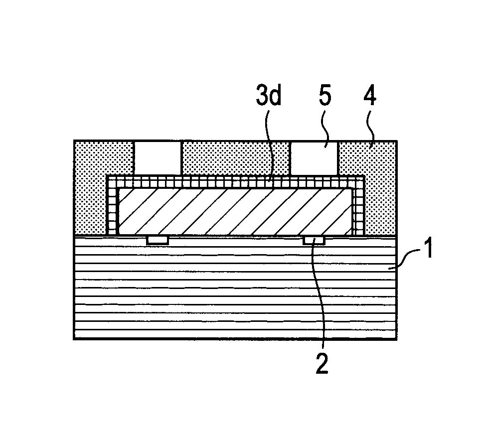
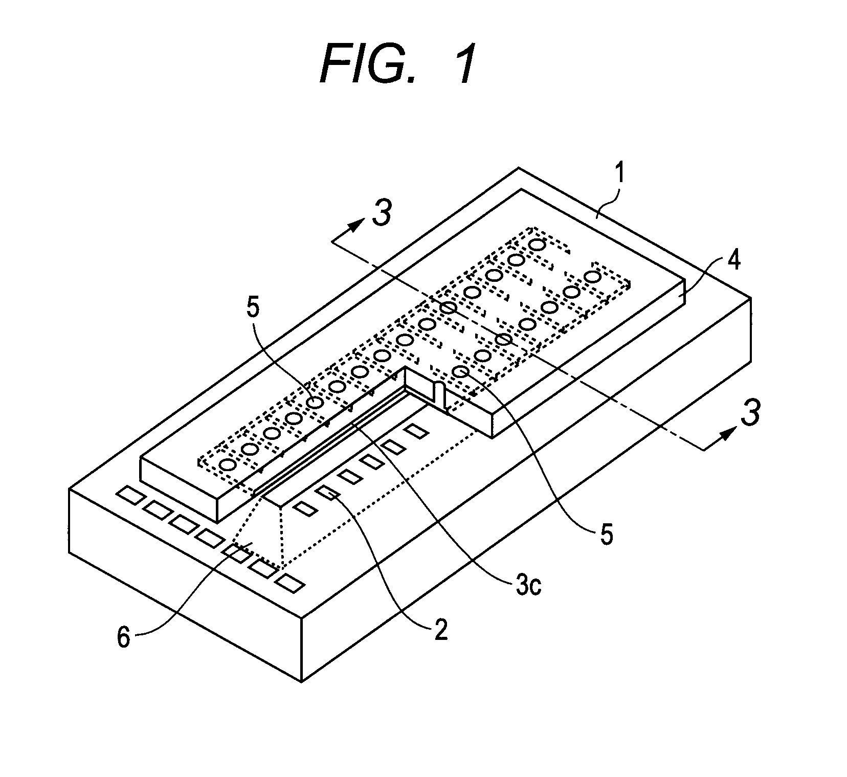
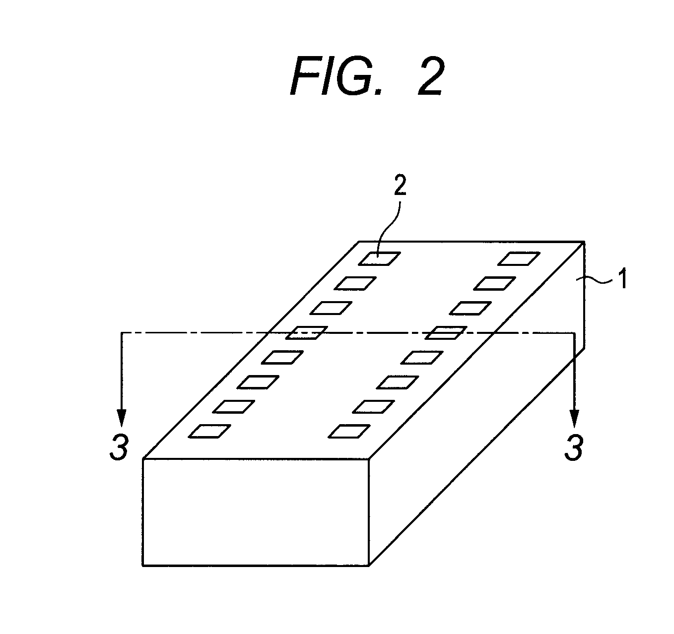
[0058]An ink jet head was produced according to the steps illustrated in FIGS. 3A to 3H. A substrate 1 illustrated in FIG. 3A was first provided. In this Example, an 8-inch silicon substrate provided with an electrothermal conversion element (heaters composed of HfB2) as an energy-generating element 2 on the silicon substrate and a laminated film (not illustrated) of SiN+Ta at forming sites for an ink flow path 3c and an ink flow path forming layer 4 was provided.

[0059]An iP-5700 resist (trade name, product of TOKYO OHKA KOGYO CO., LTD.) that is a positive resist of the NQD type was applied on the substrate 1 by a spin coating method. Thereafter, baking was conducted for 3 minutes at 90° C., thereby forming a positive resist layer 3a (FIG. 3B). Incidentally, the film thickness of the positive resist layer 3a after the baking was 7 μm.

[0060]The positive resist layer 3a was then pattern-exposed in an exposure amount of 2,000 J / m2 through a photomask by means of an i-line stepper (manu...

example 2

[0071]An ink jet head was produced in the same manner as in Example 1 except that a chemically amplified positive resist composed of the following composition was used as the positive resist to form a positive resist layer 3a.

[0072]

Polyhydroxystyrene 60% of the hydroxyl100 parts by massgroups of which had been substituted bya tert-butyl group (compound representedby the following formula (4) (n:m = 60:40))SP-172 (trade name, products of ADEKA 5 parts by massCORPORATION)SP-100 (trade name, products of ADEKA 2 parts by massCORPORATION)Ethyl lactate150 parts by mass.Formula (4)

[0073]The ink jet head was observed through a light microscope. As a result, deformation of the ink flow path 3c was not observed, but the ink ejection orifice 5 was somewhat deformed, which was however such that no problem was caused in actual use. In addition, no resist residue was observed in the ink ejection orifice 5 and the ink flow path 3c.

example 3

[0074]An ink jet head was produced in the same manner as in Example 1 except that a 10% by mass triethylene glycol divinyl ether solution was used as the coating agent in place of the 10% by mass trimethylolpropane ethoxylate trivinyl ether solution. Incidentally, the solvent of the solution was the same as in Example 1. The ink jet head was observed through a light microscope. As a result, deformation of the ink ejection orifice 5 and the ink flow path 3c was not observed. In addition, no resist residue was observed in the ink ejection orifice 5 and the ink flow path 3c.


PUM


Abstract

A process for producing an ink jet head, including forming an ink flow path pattern whose surface has been subjected to insolubilization treatment on a substrate having an energy-generating element, applying a UV curable flow path forming material on the pattern and substrate to form an ink flow path forming layer, irradiating part of the ink flow path forming layer with ultraviolet rays for development, thereby forming an ink ejection orifice, and removing the pattern, thereby forming an ink flow path. The step of forming the pattern includes applying a positive resist containing a resin having a phenolic hydroxyl group on the substrate to form a positive resist layer, patterning the positive resist layer to form an ink flow path pattern prior to insolubilization treatment, applying a coating agent containing a compound having two vinyl ether groups on the pattern, and heat-treating the pattern coated with the coating agent.

Description

BACKGROUND OF THE INVENTION[0001]1. Field of the Invention[0002]The present invention relates to a process for producing an ink jet head.[0003]2. Description of the Related Art[0004]An ink jet head applied to an ink jet recording system generally has an ink flow path, an energy-generating portion provided in a part of the ink flow path, and minute ink ejection orifice for ejecting an ink by the energy of the energy-generating portion. As a process for producing such an ink jet head, is known a process disclosed in, for example, Japanese Patent Publication No. H06-45242. According to this process, an ink flow path pattern which will become a mold of an ink flow path is formed with a photosensitive resin material on a substrate on which energy-generating elements have been formed as an energy-generating portion. A coating resin layer which will become a nozzle material is formed on the substrate so as to coat the ink flow path pattern. Ink ejection orifices communicating with the ink ...

Claims


Application Information

Patent Timeline
Patent Type & Authority Patents(United States)
IPC IPC(8): B41J2/16
CPCG03F7/0035G03F7/022G03F7/038G03F7/0392G03F7/40B41J2/1603B41J2/1629B41J2/1631B41J2/1639B41J2/1645G03F7/0751G03F7/0755G03F7/325
Inventor SHIBA, SHOJIIKEDA, MASUMI
Owner CANON KK
Why Eureka
Try Eureka