
Resist composition for electron beam, EUV or X-ray

a technology of resist composition and electron beam, applied in the field of resist composition, can solve the problems of resolution, sensitivity decrease, and inability to meet all, and achieve the effect of improving the performance of fine processing of semiconductor devices

Inactive Publication Date: 2009-04-21
FUJIFILM HLDG CORP +1
View PDF23 Cites 8 Cited by
  • Summary
  • Abstract
  • Description
  • Claims
  • Application Information

AI Technical Summary

Benefits of technology

[0011]An object of the present invention is to provide a resist composition which resolve problems in the techniques for improving the performance in fine processing of semiconductor device using an electron beam, EUV or an X-ray.
[0013]A still another object of the present invention is to provide a positive resist composition that fulfills characteristics of rectangular pattern profile and edge roughness as well as sensitivity and resolution in case of using an electron beam, EUV or an X-ray.

Problems solved by technology

On the other hand, however, the transmittance of electron beam increases, resulting in decrease in sensitivity.
Thus, a trade off relation between the sensitivity and the resolution, resist profile and edge roughness exists in the electron beam lithography, and it is a problem to be solved to fulfill requirements for both the sensitivity and the resolution, resist profile and edge roughness.
However, these attempts do not solve the problem to fulfill all requirements of high sensitivity, high resolution, good rectangular resist profile and excellent edge roughness.
However, it could not be achieved to fulfill all characteristics of the sensitivity, resolution, resist profile and edge roughness upon irradiation of electron beam or X-ray by using such alkali-soluble resins.
However, the trade off relation between the sensitivity and the resolution, resist profile and edge roughness upon irradiation of electron beam or X-ray cannot be overcome by using such acid generators.
However, these crosslinking agents are unstable to heat and have a problem of preservation stability of a resist solution.
The resist compositions described in Japanese Patent 3,000,740, JP-A-9-166870 and JP-A-2-15270 are also insufficient for meeting characteristic requirements of high sensitivity, high resolution, good rectangular resist profile and excellent edge roughness upon irradiation of electron beam or X-ray.
Therefore, it is difficult to fulfill requirements for sufficiently high sensitivity, sufficiently high resolution, good rectangular resist profile and excellent edge roughness all together in hitherto known techniques and it has been strongly desired to solve the problem.

Method used


Image

  • Resist composition for electron beam, EUV or X-ray
  • Resist composition for electron beam, EUV or X-ray
  • Resist composition for electron beam, EUV or X-ray

Examples


experimental example

Measurement of Reduction Potential

[0324]The reduction potential of acid generator was measured by a cyclic voltammetry method. Specifically, each of the acid generators shown in Table 1 below was dissolved in distilled acetonitrile under argon atmosphere to prepare a 1 mM solution of the acid generator for the measurement. A 0.1 mM solution of tetrabutylammonium perchlorate was used as a supporting electrolyte. With respect to electrodes, MP-2 (manufactured by Yanaco LID Co., Ltd.), C-2U (manufactured by Yanaco LID Co., Ltd.) and Ag / AgCl were used as a working electrode, a counter electrode and a reference electrode, respectively. The measurement was conducted at 23.5° C. The scanning speed was 50 mV / cm2. Since the acid generator was decomposed by reduction and the reaction was irreversible, only a reduction peak was observed.

[0325]

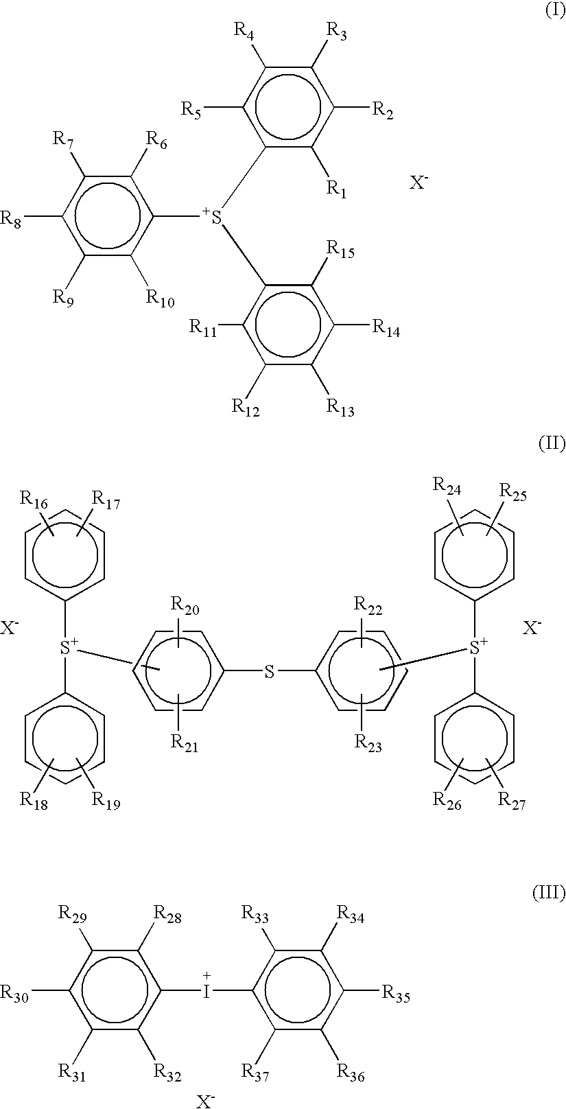
TABLE 1ReductionPotentialChemical Structure(vs SCE)−1.14 V−0.78 V−0.61 V−0.74 V−0.68 V−0.77 V−0.64 V

(1) Synthesis of Compound of (A1)

[0326]In 200 ml of b...


PUM


Abstract

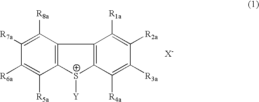
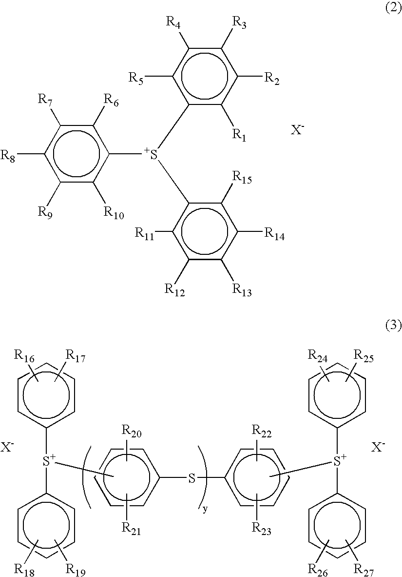
A resist composition for an electron beam, EUV or X-ray comprising (A1) a compound that has a reduction potential higher than that of diphenyl iodonium salt and generates an acid upon irradiation of an actinic ray or radiation.

Description

FIELD OF THE INVENTION[0001]The present invention relates to a resist composition suitable for use in an ultra-micro lithographic process, for example, the production of VLSI and high-capacity microchips, and other photofabrication processes. More specifically, the present invention relates to a positive resist composition and negative resist composition capable of forming high precision patterns using an electron beam, EUV or an X-ray.BACKGROUND OF THE INVENTION[0002]In integrated circuits, the degree of integration has more and more increased and in the production of a semiconductor substrate such as VLSI, processing of super-fine patterns composed of line width having a half-micron or less has been required. In order to satisfy such a requirement, the wavelength of an exposure apparatus used for a photolithography has more and more shortened and at present, the use of a far ultraviolet light and an excimer laser (e.g., XeCl, KrF or ArF) is investigated. Furthermore, the formation...

Claims


Application Information

Patent Timeline
IPC IPC(8): G03C1/73G03F7/029G03F7/039G03F7/20G03F7/30G03F7/004G03F7/038
CPCG03F7/0045G03F7/0382G03F7/0392Y10S430/143Y10S430/12Y10S430/122Y10S430/121Y10S430/167Y10S430/106Y10S430/126Y10S430/123H01L21/027H01L21/0271
Inventor MIZUTANI, KAZUYOSHITAKAHASHI, HYOU
Owner FUJIFILM HLDG CORP
Learn More