Reflective insulation

a technology of reflective insulation and insulation layer, which is applied in the field of reflective insulation, can solve the problems of increasing the temperature of the roof and exterior walls of the building, preventing the effect of radiant barriers, and increasing the temperature, so as to eliminate the risk of material delamination and less flammability. , the effect of less flammability

Inactive Publication Date: 2012-11-13
SILVERCOTE
View PDF20 Cites 6 Cited by
  • Summary
  • Abstract
  • Description
  • Claims
  • Application Information

AI Technical Summary

Benefits of technology

[0017]The reflective insulation system of the present invention has many advantages over prior art reflective insulation systems. The inner layer of the reflective insulation system of the present invention is fiberglass insulation, which is much less flammable than the foam and bubble-type material used in inner layers of prior art reflective insulation systems. Since the outer layers of the reflective insulation system are not fused to the center layer with heat, vapor barrier materials that perform better in flame and smoke tests can be used to construct the reflective insulation system. The hot melt glue allows fiberglass insulation to be bonded to less flammable vapor barriers. It is not necessary to dry the hot melt glue that is used to bond the layers together, eliminating the risk of delamination of the materials due to failure of the adhesive to properly dry and bond.

Problems solved by technology

For example, radiant heat from the sun travels through space and strikes the roof of a building and exterior walls of a building, causing the roof and exterior walls of the building to increase in temperature.
Warmer surfaces inside the building radiate heat to the inner surfaces of the walls and the roof of the building, causing them to increase in temperature.
Radiant barriers and reflective insulation systems reduce radiant heat transfer between surfaces across open spaces, which is a significant contributor to heat gain during warm months and heat loss during cold months.
Radiant barriers do not prevent heat on one side of the reflected material from being conducted to the second side of the reflective material.
One significant problem with existing reflective insulation systems is that the layer of plastic bubbles or plastic foam is highly flammable.
The flammability of the layer of plastic bubbles or foam greatly limits the number of applications this type of reflective insulation system can be used in.
This process restricts the types of vapor barriers that can be used in these reflective insulation systems.
Most notably, polyethylene or polypropylene vapor barriers that are least flammable cannot currently be used in these reflective insulation systems, since they do not readily bond by heating and fusing.
The vapor barriers that can be bonded by heating and fusing are more flammable, adding to the flammability problem.
Water-based adhesives would not work well for laminating a thin layer of insulation between two layers of facing, since the air movement around the adhesive is very restricted.
The restricted air movement around the adhesive would greatly increase the time required for the water-based adhesive to cure and may even prevent the adhesive from ever properly curing.
If a water-based adhesive freezes before it properly dries, the water-based adhesive will never properly cure and will not provide a sufficient bond between the materials being glued together.
This is especially problematic in cold weather climates.

Method used


Image

  • Reflective insulation
  • Reflective insulation
  • Reflective insulation

Examples


Embodiment Construction

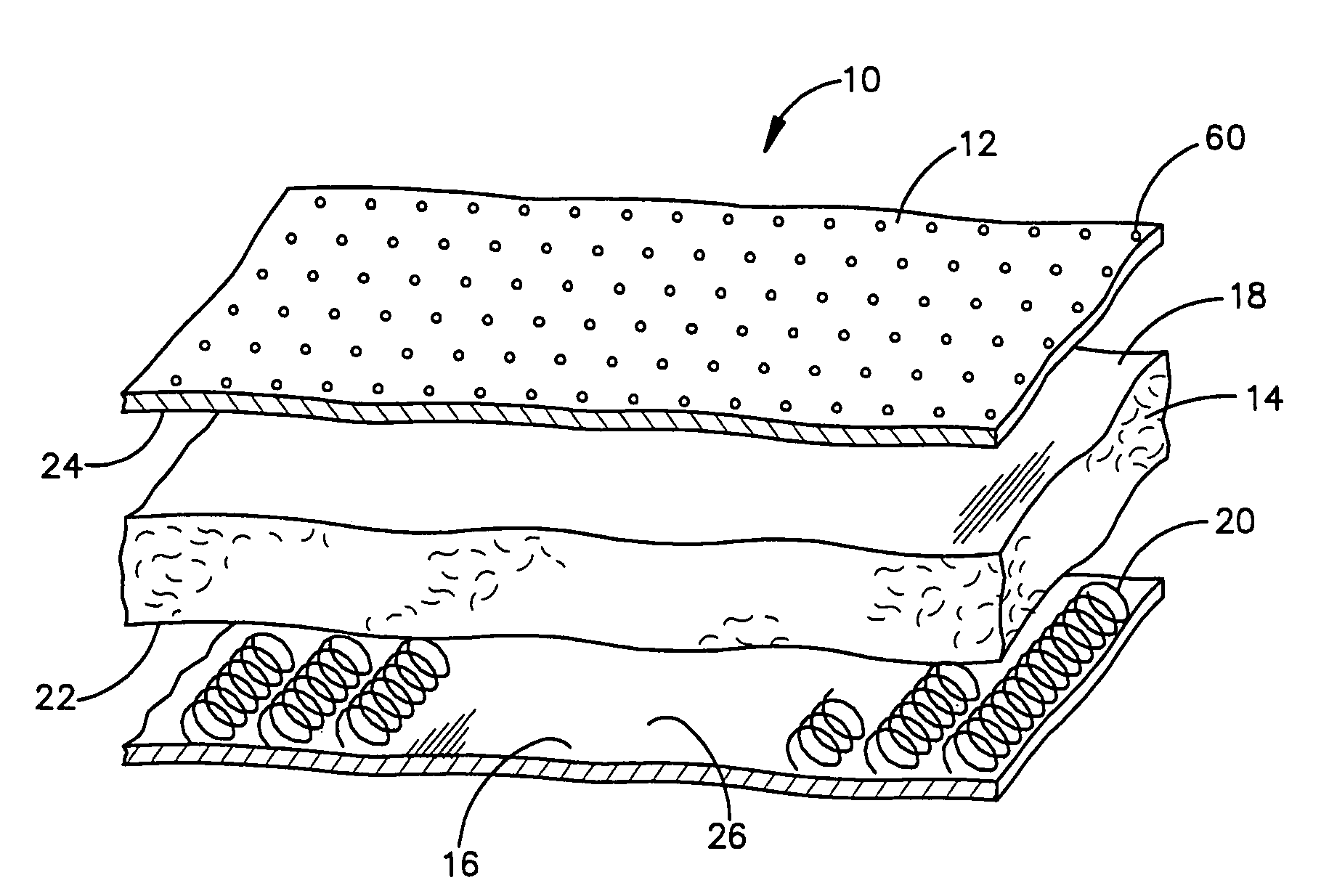
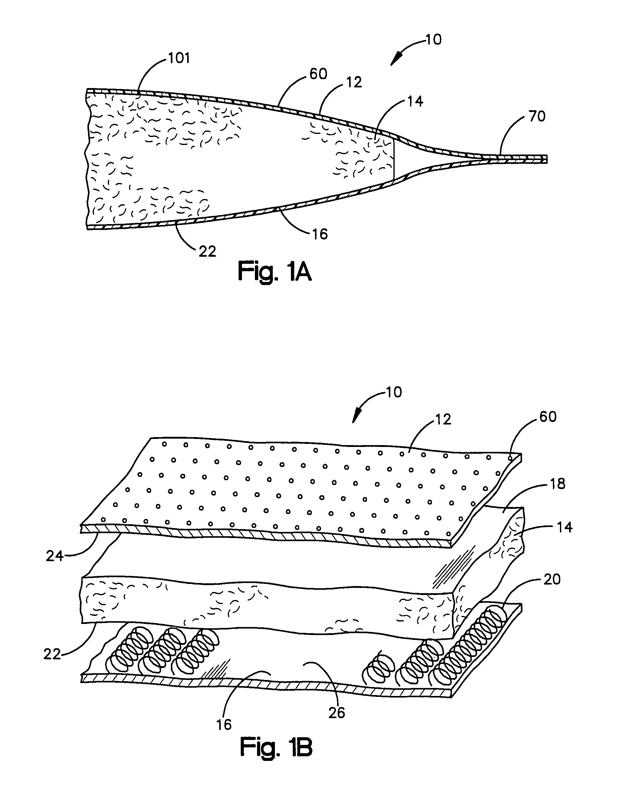
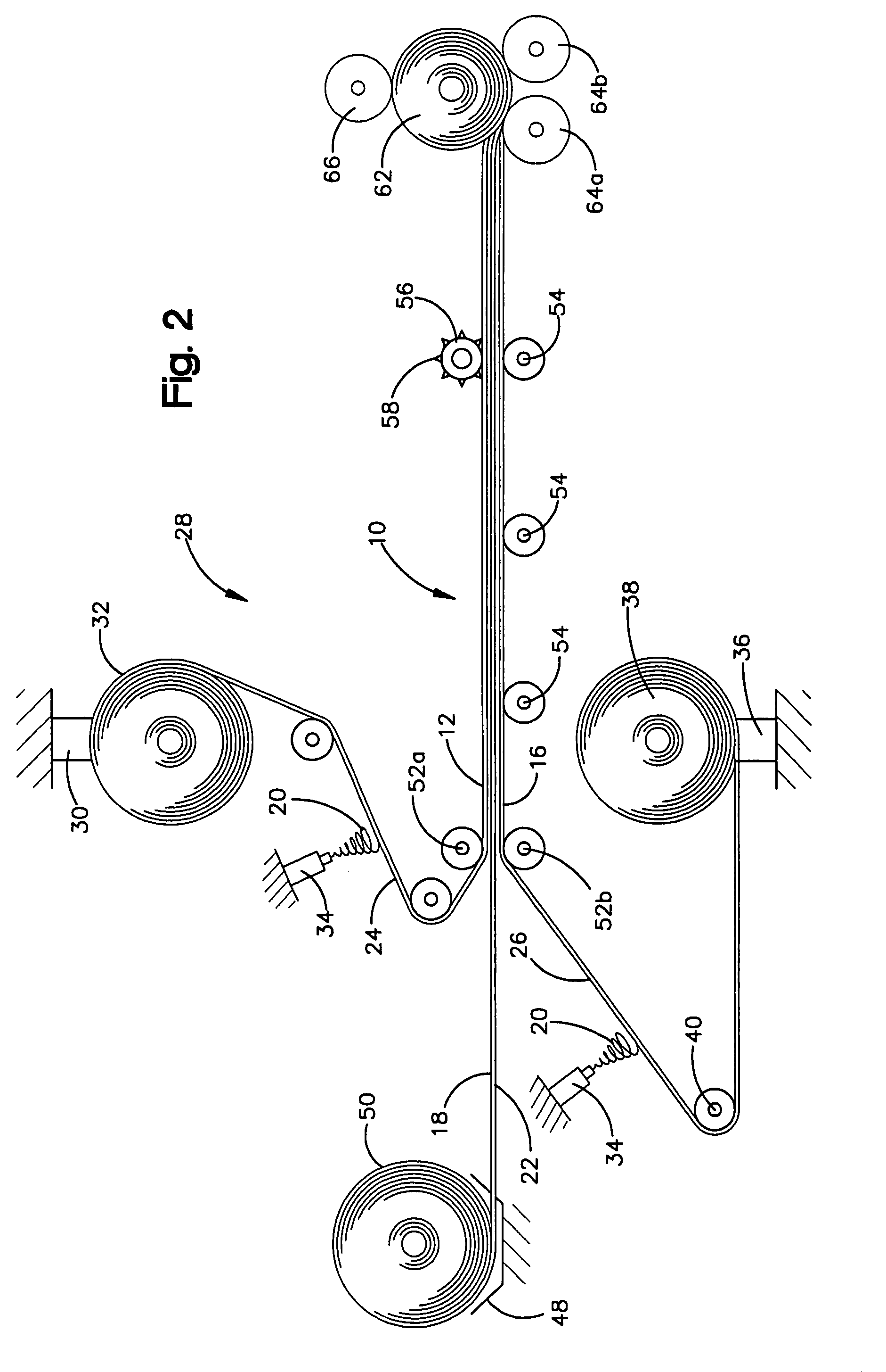
[0030]Referring to FIGS. 1A and 1B, the present invention is directed to a reflective insulation system 10. The reflective insulation system 10 includes a reflective layer 12, a layer of fiberglass 14, and a vapor barrier layer 16. A first side 18 of the layer of fiberglass 14 is bonded to the reflective layer 12 by a deposit of hot melt glue 20 (FIG. 2). The vapor barrier layer 16 is bonded to a second side 22 of the fiberglass layer 14 by a second deposit of hot melt glue 20.

[0031]The reflective layer 12 has an outer layer that is made from a reflective material such as aluminum. In the exemplary embodiment, the reflective layer 12 is a laminate that includes a layer of aluminum foil adhered to a polyester film by a flame resistant adhesive. In the exemplary embodiment, the aluminum foil of the reflective layer laminate is 0.0003 inches thick and the polyester film is 0.00048 inches thick. The polyester film strengthens the reflective layer 12, preventing it from being torn easily...


PUM

PropertyMeasurementUnit
thickaaaaaaaaaa
thickaaaaaaaaaa
thickaaaaaaaaaa

Abstract

A reflective insulation system. The reflective insulation system includes a reflective layer such as aluminum, a layer of fiberglass, and a layer of vapor retarding material. A first side of the layer of fiberglass is bonded to the reflective layer by a deposit of hot melt glue. The second side of the layer of fiberglass is bonded to the layer of vapor retarding material by a second deposit of hot melt glue. The vapor retarding layer may be a plastic material, such as polypropylene or a reflective material, such as aluminum. In an alternate construction, the reflective layer has a transverse dimension that is narrower than the vapor retarding material such that edge portions of the reflective layer are spaced inwardly with respect to edges of said vapor retarder material. A strip of adhesive tape, preferably foil tape, overlies and secures edge portions of the reflective and vapor retarder layers.

Description

RELATED APPLICATIONS[0001]The present application is a continuation-in-part application of U.S. application Ser. No. 10 / 947,756, filed Sep. 23, 2004, now abandoned, which is a continuation of U.S. application Ser. No. 10 / 083,205, filed Feb. 26, 2002 entitled REFLECTIVE INSULATION, now U.S. Pat. No. 6,797,356, which is a non-provisional application of provisional application Ser. No. 60 / 271,794, filed Feb. 27, 2001.TECHNICAL FIELD[0002]The present invention relates to reflective insulation and, in particular, reflective insulation that includes a layer of fiberglass insulation bonded to a layer of reflective material and a layer of vapor retarder material.BACKGROUND ART[0003]Radiation is the transfer of heat or energy from a hot surface to a cold surface through air or a vacuum. For example, radiant heat from the sun travels through space and strikes the roof of a building and exterior walls of a building, causing the roof and exterior walls of the building to increase in temperature...

Claims


Application Information

Patent Timeline
Patent Type & Authority Patents(United States)
IPC IPC(8): B32B3/04B32B3/10B32B29/02B32B27/32B32B15/14B32B27/12B32B27/04D04H13/00D04H3/00D04H5/00D04H1/00B32B5/02B32B15/08B32B15/20B32B17/02B32B27/36E04B1/76E04B1/78
CPCB32B5/02B32B15/14B32B15/20B32B17/02B32B27/32B32B27/36B32B29/02E04B1/78B32B7/12B32B27/12B32B3/266B32B15/08Y10T428/24322E04B2001/7691B32B2262/101B32B2307/304B32B2307/416B32B2307/7246B32B2419/00B32B2419/06Y10T428/2419Y10T428/24273Y10T428/24331Y10T442/678Y10T442/2746Y10T442/674Y10T442/656Y10T442/2738Y10T442/693Y10T442/654
Inventor ZUPON, LAWRENCEDEJARLAIS, DAVIDGAMBATESE, JAMESNEFF, STEPHEN
Owner SILVERCOTE
Why Eureka
Try Eureka