Thin-film magnetic head, method of manufacturing the same, head gimbal assembly, and hard disk drive

a technology of thin film and magnetic head, which is applied in the direction of magnetic recording, instruments, data recording, etc., can solve the problems of difficult to increase the recording density the frying height is difficult to be smaller in the conventional pmr, and the protruding magnetic pole layer is difficult to etc., to suppress the protruding magnetic pole layer, suppress the heat generation of the thin film coil, and suppress the effect of the protrud

Active Publication Date: 2012-11-13
HEADWAY TECH INC +1
View PDF11 Cites 49 Cited by
  • Summary
  • Abstract
  • Description
  • Claims
  • Application Information

AI Technical Summary

Benefits of technology

[0013]Such protrusion of the magnetic pole layer is mainly caused by heat generation of the thin-film coil. Therefore, to suppress the protrusion of the magnetic pole layer, it is sufficient to suppress the heat generation of the thin-film coil. Generally, the heat generated from the conductor through which the electric current flows is called Joule heat and is known to be proportional to the square of the magnitude of electric current and the electric resistance of the conductor (Joule's law). Accordingly, to suppress the heat generation of the thin-film coil, it is sufficient to reduce the electric resistance of the thin-film coil.
[0014]The electric resistance of the thin-film coil is inversely proportional to the sectional area of the thin-film coil (the area of the section in the direction intersecting the direction in which the electric current flows). Therefore, to reduce the electric resistance of the thin-film coil, it is sufficient to increase the sectional area of the thin-film coil. By reducing the number of windings (also called the number of turns) wound around the magnetic pole layer of the thin-film coil, the thin-film coil is able to be made thick and the sectional area is able to be made large. However, this reduces the intensity of the magnetic field generated by the thin-film coil, causing a problem of decreasing the writing characteristics of the PMR (for example, the overwrite characteristics).
[0015]Further, the sectional area of the thin-film coil is able to be increased also by widening the width of the thin-film coil or by increasing the thickness of the thin-film coil without changing the number of turns of the thin-film coil. For example, in the case of the PMR 600, the sectional area of the thin-film coil is able to be increased even by widening the width w602 of the thin-film coil 602 or increasing the thickness h602.

Problems solved by technology

However, when the medium-opposing surface projects as in the above-described PMR 600, the PMR collides with the recording medium and becomes more likely to break.
For this reason, it is difficult to make the frying height smaller in the conventional PMR.
As a result, it is very difficult to increase the recording density in the conventional PMR.

Method used


Image

  • Thin-film magnetic head, method of manufacturing the same, head gimbal assembly, and hard disk drive
  • Thin-film magnetic head, method of manufacturing the same, head gimbal assembly, and hard disk drive
  • Thin-film magnetic head, method of manufacturing the same, head gimbal assembly, and hard disk drive

Examples


first embodiment

Structures of Thin-Film Magnetic Head

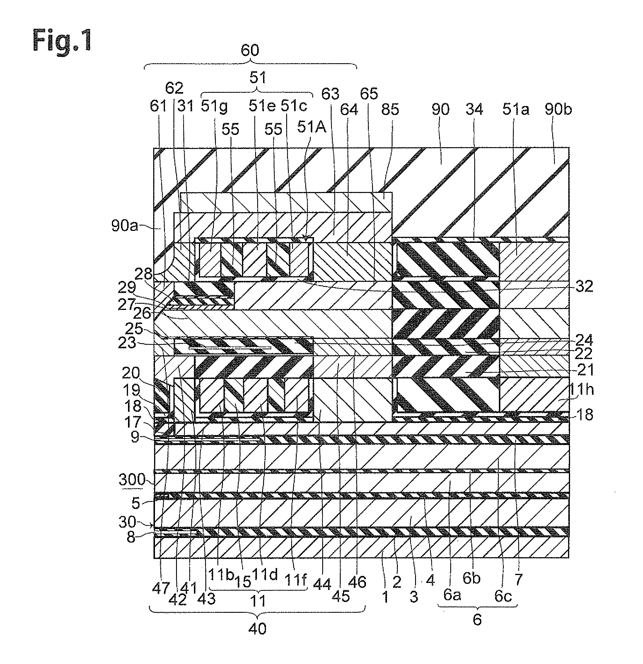
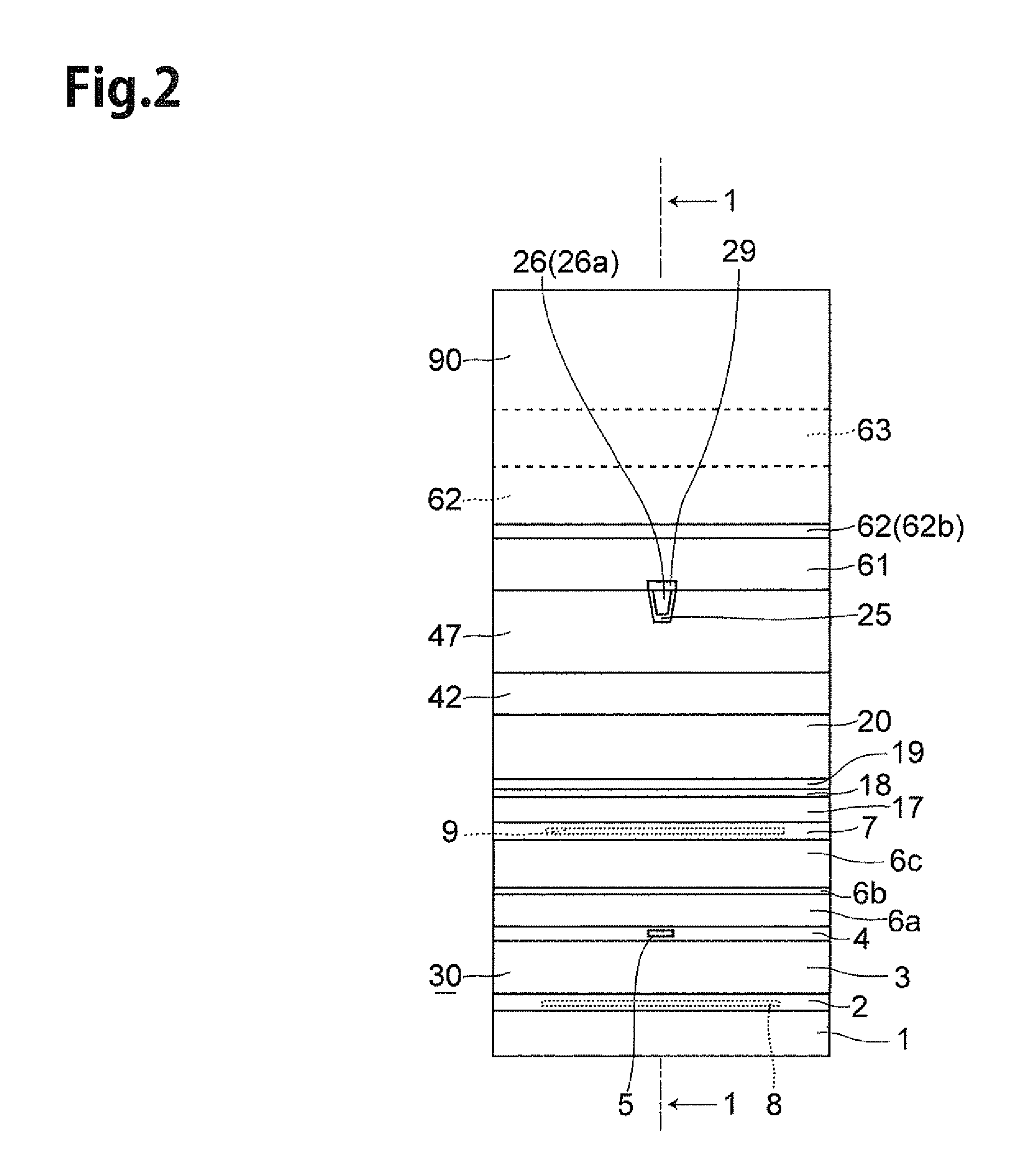
[0107]To begin with, the structure of a thin-film magnetic head of perpendicular magnetic recording type according to the first embodiment of the present invention will be explained with reference to FIG. 1 to FIG. 11. Here, FIG. 1 is a sectional view of the thin-film magnetic head 300 according to a first embodiment of the present invention taken along the line 1-1 of FIG. 2, along by a direction intersecting its air bearing surface (which will hereinafter be referred to as “ABS”), FIG. 2 is a front view illustrating the ABS 30 of the thin-film magnetic head 300. FIG. 3 is a plan view illustrating a lower thin-film coil 11. FIG. 4 is a plan view illustrating an upper thin-film coil 51. FIG. 5 is a plan view illustrating a principal part of the lower thin-film coil 11. FIG. 6 is a sectional view illustrating an enlarged principal part of the ABS 30. FIG. 7 (a) is a sectional view of an enlarged principal part of a lower front shield part 42, FIG....

modified example 1

[0234]The thin-film magnetic head 300 may have lower front shield part 242, 243 illustrated in FIG. 42(a), (b) in place of the lower front shield part 42. The lower front shield parts 242, 243 have respective tilted lower end faces 242b, 243b.

[0235]In the case of the above-described lower front shield part 42, the tilted lower end face 42b is in contact with the tilted upper end face 20a of the opposing insulating layer 20 and the upper end face of the insulating layer 19 but not in contact with the upper end face 41a of the connecting shield part 41. In contrast, in the case of the lower front shield part 242, the tilted lower end face 242b is in contact with the tilted upper end face 20a and the upper end face of the insulating layer 19 and also in contact with the upper end face of a connecting shield part 241. Further, the tilted lower end face 243b is in contact with the tilted upper end face 20a and the upper end face of the insulating layer 19 and also in contact with the up...

modified example 2

[0237]The above-described thin-film magnetic head 300 may have the upper front shield part 62B as illustrated in FIG. 10 (a) in place of the above-described upper front shield part 62. The upper front shield part 62B is different in that it has a shield connecting part 62d in place of the shield connecting part 62c, as compared with the upper front shield part 62. The shield connecting part 62d is different in that it is not have the lateral flat part 62c1, as compared with the shield connecting part 62c.

[0238]The thin-film magnetic head 300 may have the upper front shield part 62D as illustrated in FIG. 10 (b) in place of the upper front shield part 62. The upper front shield part 62D is different in that it has a shield connecting part 62e in place of the shield connecting part 62c, as compared with the upper front shield part 62. The shield connecting part 62e is different in that it is not have the longitudinal flat part 62c2, as compared with the shield connecting part 62c.

[0...


PUM

PropertyMeasurementUnit
heightaaaaaaaaaa
widthaaaaaaaaaa
widthaaaaaaaaaa

Abstract

A thin-film magnetic head is constructed such that a main magnetic pole layer, a write shield layer, a gap layer, and a thin-film coil are laminated on a substrate. The thin-film magnetic head has a shield magnetic layer. The shield magnetic layer is connected to the main magnetic pole layer. The shield magnetic layer has a lower front shield part. A front end angle representing an angle formed between a front end face of the lower front shield part and a lower end face is set at an obtuse angle. The front end face is disposed in the medium-opposing surface. The lower end face is disposed at a position closest to the substrate in the lower front shield part.

Description

BACKGROUND[0001]1. Field of the Invention[0002]The present invention relates to a thin-film magnetic head which performs a magnetic recording action by a perpendicular magnetic recording scheme, a method of manufacturing the same, a head gimbal assembly, and a hard disk drive.[0003]2. Related Background Art[0004]A hard disk drive has a large recording capacity and is used as the heart of a storage device. The hard disk drive records and reproduces data to / from a hard disk (recording medium) by a thin-film magnetic head.[0005]The thin-film magnetic heads can roughly be classified according to their recording schemes into those of longitudinal magnetic recording type and those of perpendicular magnetic recording type. The longitudinal magnetic recording scheme records data in a (longitudinal) direction within a recording surface of a hard disk (recording medium), while the perpendicular magnetic recording scheme records data such that the direction of recording magnetization formed in...

Claims


Application Information

Patent Timeline
Patent Type & Authority Patents(United States)
IPC IPC(8): G11B5/31
CPCG11B5/1278G11B5/3116G11B5/3163
Inventor SASAKI, YOSHITAKAITO, HIROYUKITANEMURA, SHIGEKISATO, KAZUKIIIJIMA, ATSUSHI
Owner HEADWAY TECH INC
Why Eureka
Try Eureka